What is BEAM robotics anyway?
When I first started robotics, I was quite intimidated by the concept of programming. My understanding was informed by the Hollywood stereotype with a sulking nerd character striking keys quicker than a court reporter all the while switching between walls of scrolling text on at least three monitors. Hollywood did get the multi-monitor setup right and I do tend to brood as I work in VS Code.
Back on topic, in late middle school / early high school I was introduced to the concept of BEAM robotics as pioneered by Mark Tilden. BEAM. standing for Biological, Electrical, Aesthetic, Mechanical, is a robotics philosophy that reacted to the overly complicated robot systems running on CPUs and microcontrollers. Tilden noticed that these traditional robots were functionally brittle. If a failure happened within the robot or if the environment was not within the range of expected states, then the robot would fail to achieve its task. Taking inspiration from nature, he recast the problem to build robots that could survive without people. These robots need to be adaptive to an un-modellable environment. They need to be simple enough to not have their own complexity be a source of system failure (i.e., survive in the wild). Additionally, he wanted these robots to be agents, life-forms even, in their own right instead of electro-mechanical tools.
His philosophy spawned a maker community with the goal of filling out the bestiary of robot agents that could feasibly be built. This community had the advantage of lower barrier to entry than traditional robotics at the time. Instead of having to purchase a microcontroller (and programmer/compiler) costing hundreds of dollars, these hobbyist to could tear open a VCR or head over to their local Radio Shack to scavenge all the parts necessary to exhibit interesting behavior. This was a time where through-hole components and DIP ICs could be easily sourced. The main challenges for the community were power and elegant mechanical solutions.
In the 90s and 00s, both battery and solar technology at an applicable scale for these robots were rather crude compared to todays standards. Solar robots, which aligned well with the biological tenant of BEAM, were particularly popular. Powering these robots became of challenge of saving up just enough energy to power a simple circuit. As an example, a particular robot called a solar roller was designed with the purpose of moving as far, fast as possible. It consisted of a solar cell, a large capacitor, a solar engine circuit, and a motor. Once the capacitor was topped off the solar engine fired; driving a motor to propel the robot.
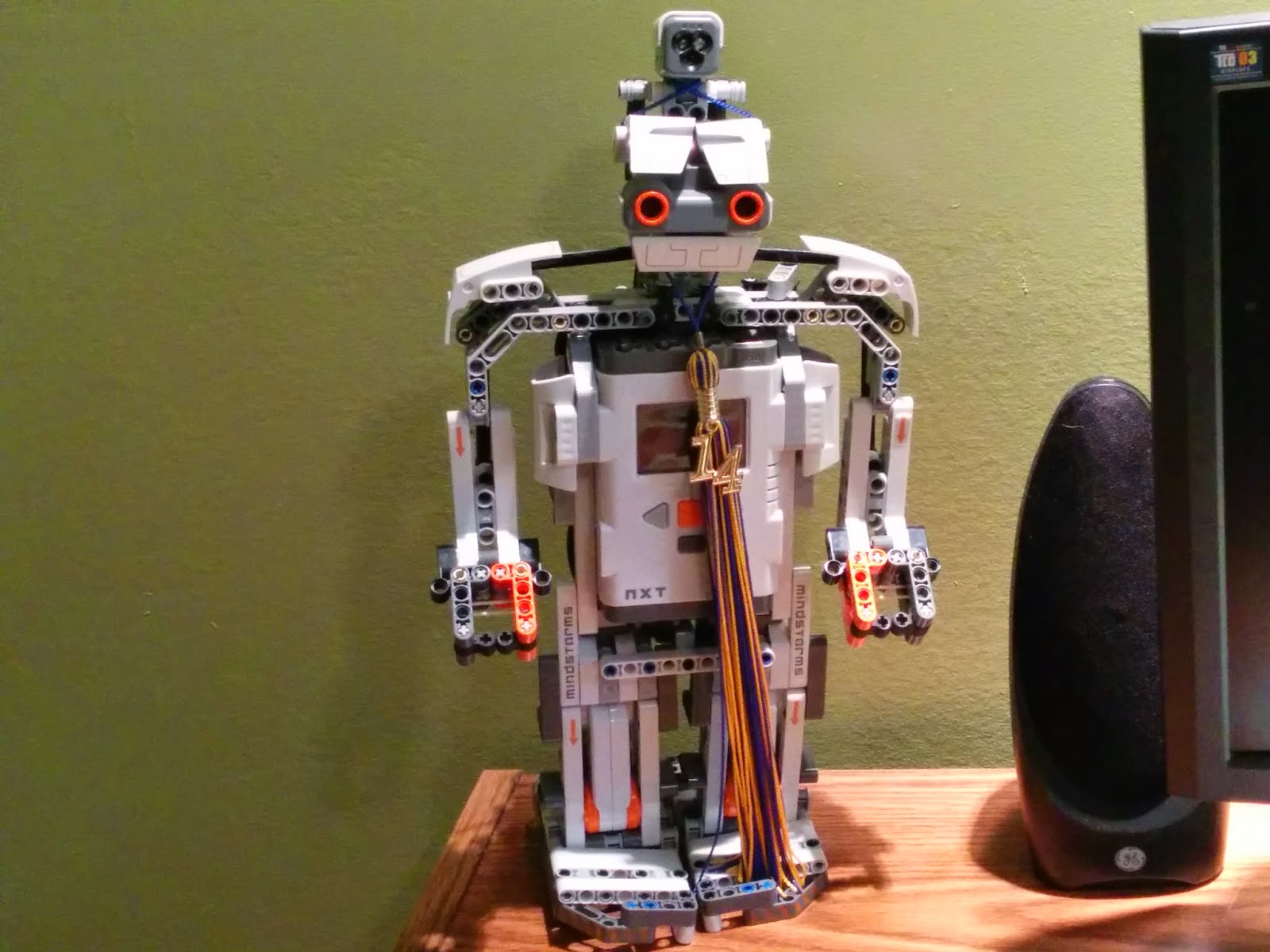
Beginners could often start with very simple circuits; producing robots with simple behaviors. Then as their skills progressed, they could combine these simple circuits to generate slightly more complex behavior. Taken to the highest caliber, one could build something akin to Mark Tilden’s Walkman VBug robot.
This was all very alluring to me as a young teenager having yet to start my journey into robotics. Even now, the simplifying philosophy is a nice break from more traditional robotics.
My Robots
The Beetles
The first real robot that I constructed was a beetle robot from instructions found on Instructables. Not really sure if it is officially a BEAM robot but it certainty seems like it fits the philosophy. The robot was designed by Jerome Demers. It consisted of two switches, two motors, AA battery box, and some crafting supplies. See the original instructions here. Please do look at some of his other projects he has a lot of interesting content.
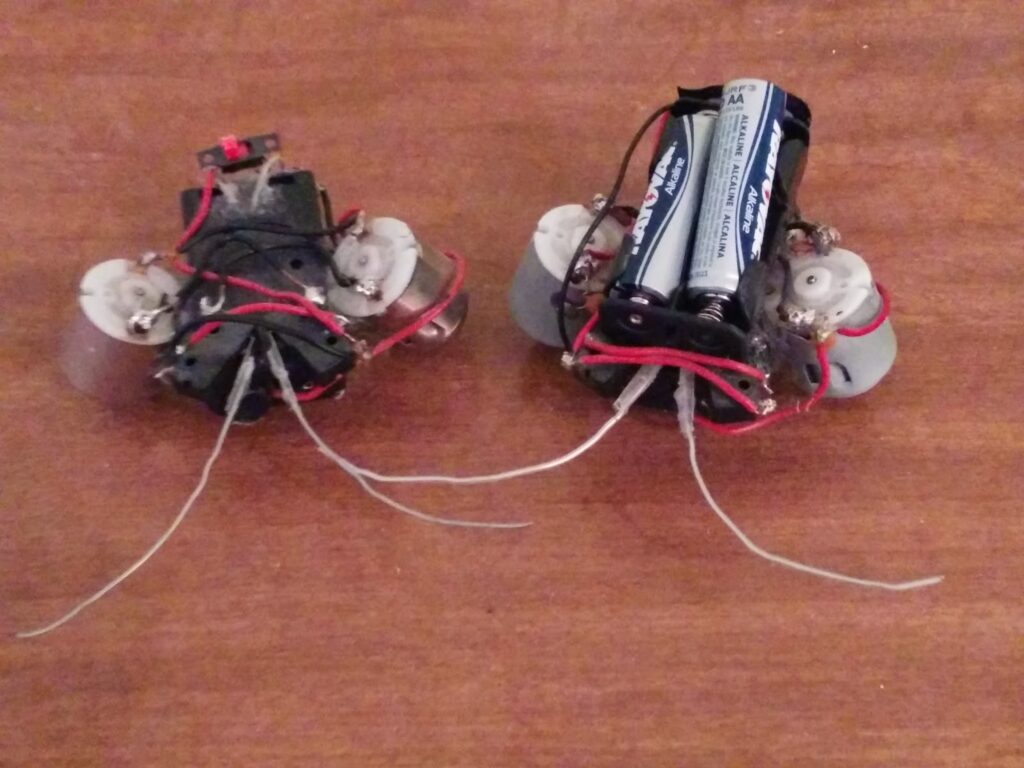
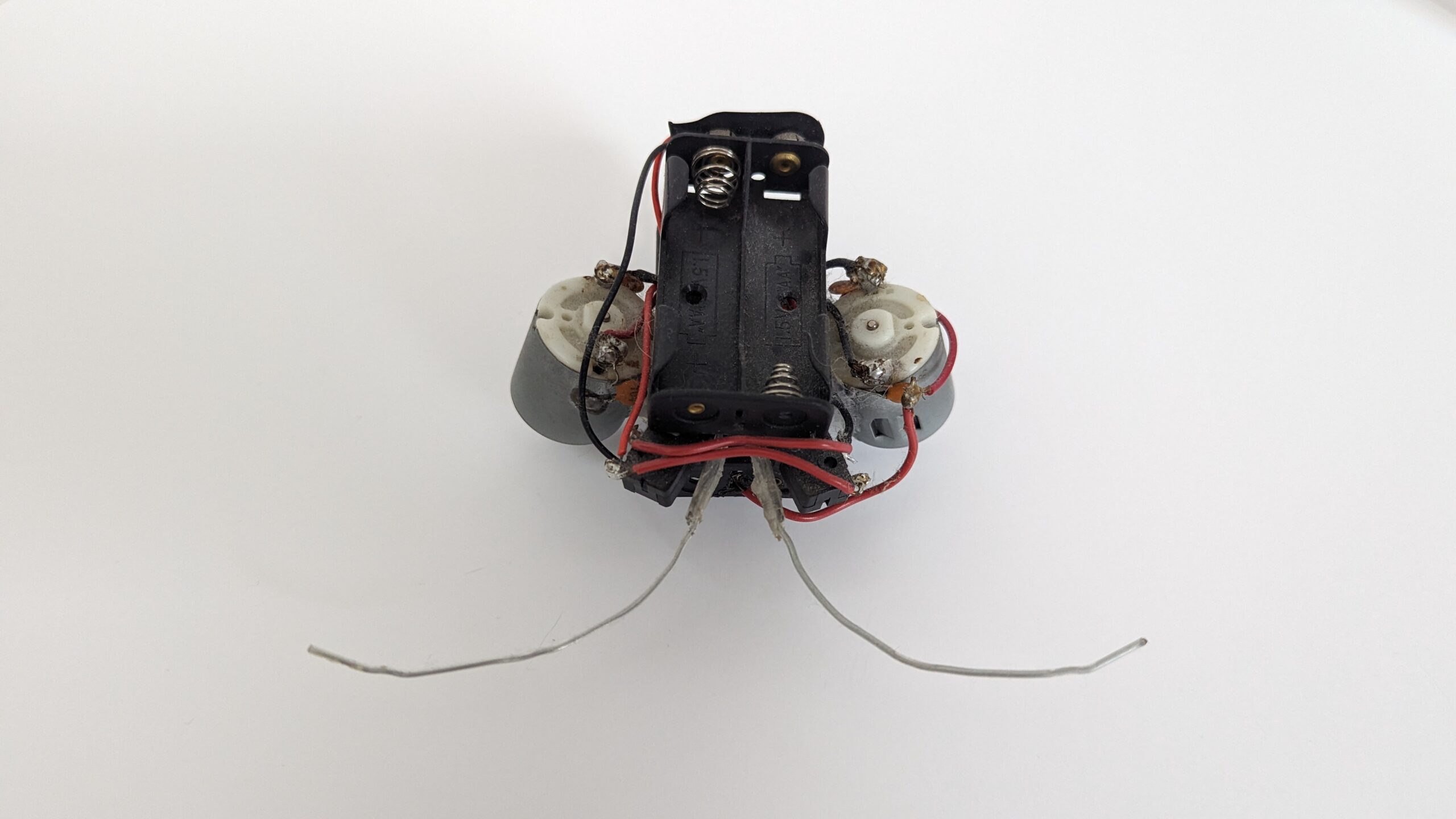
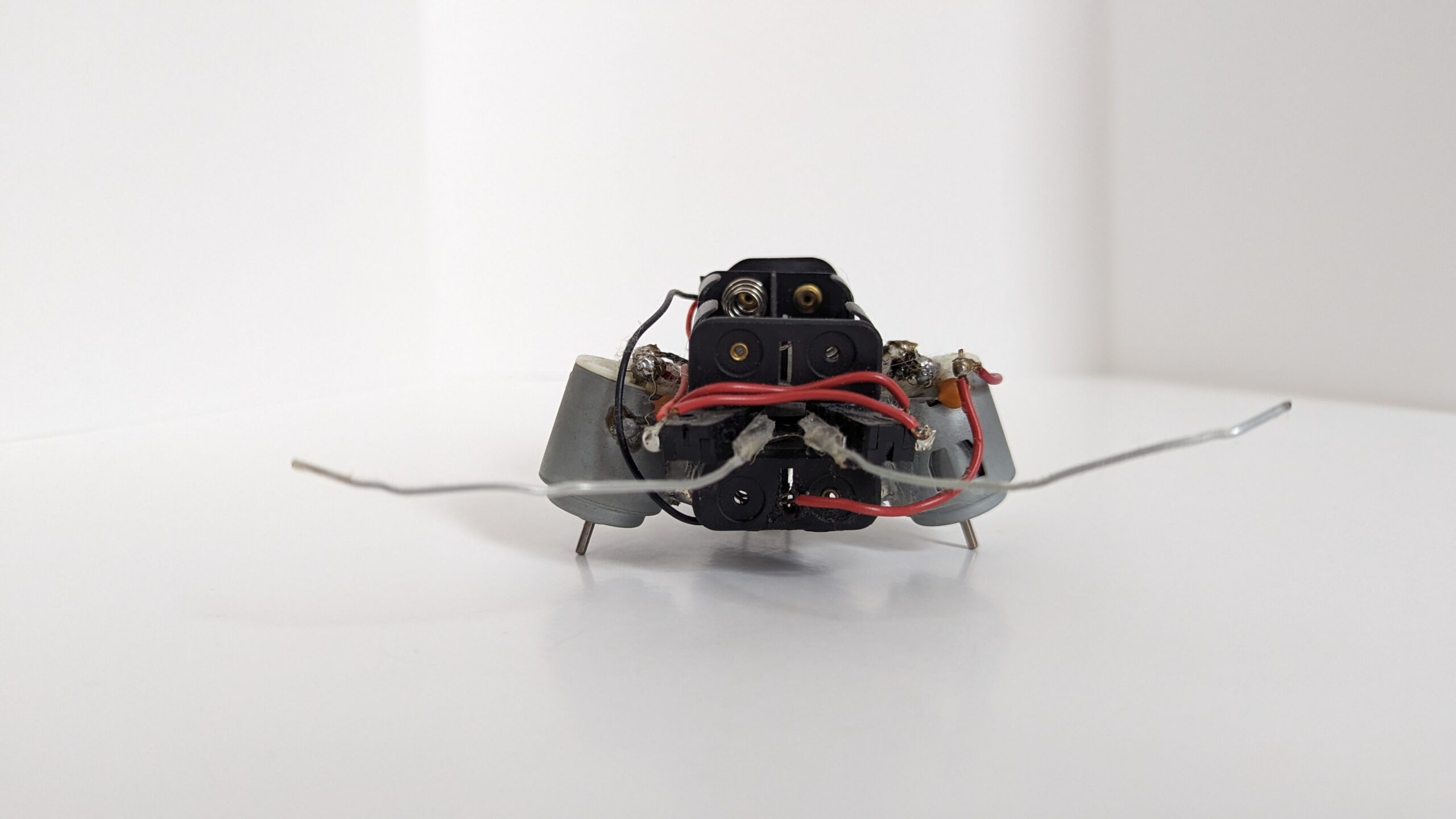
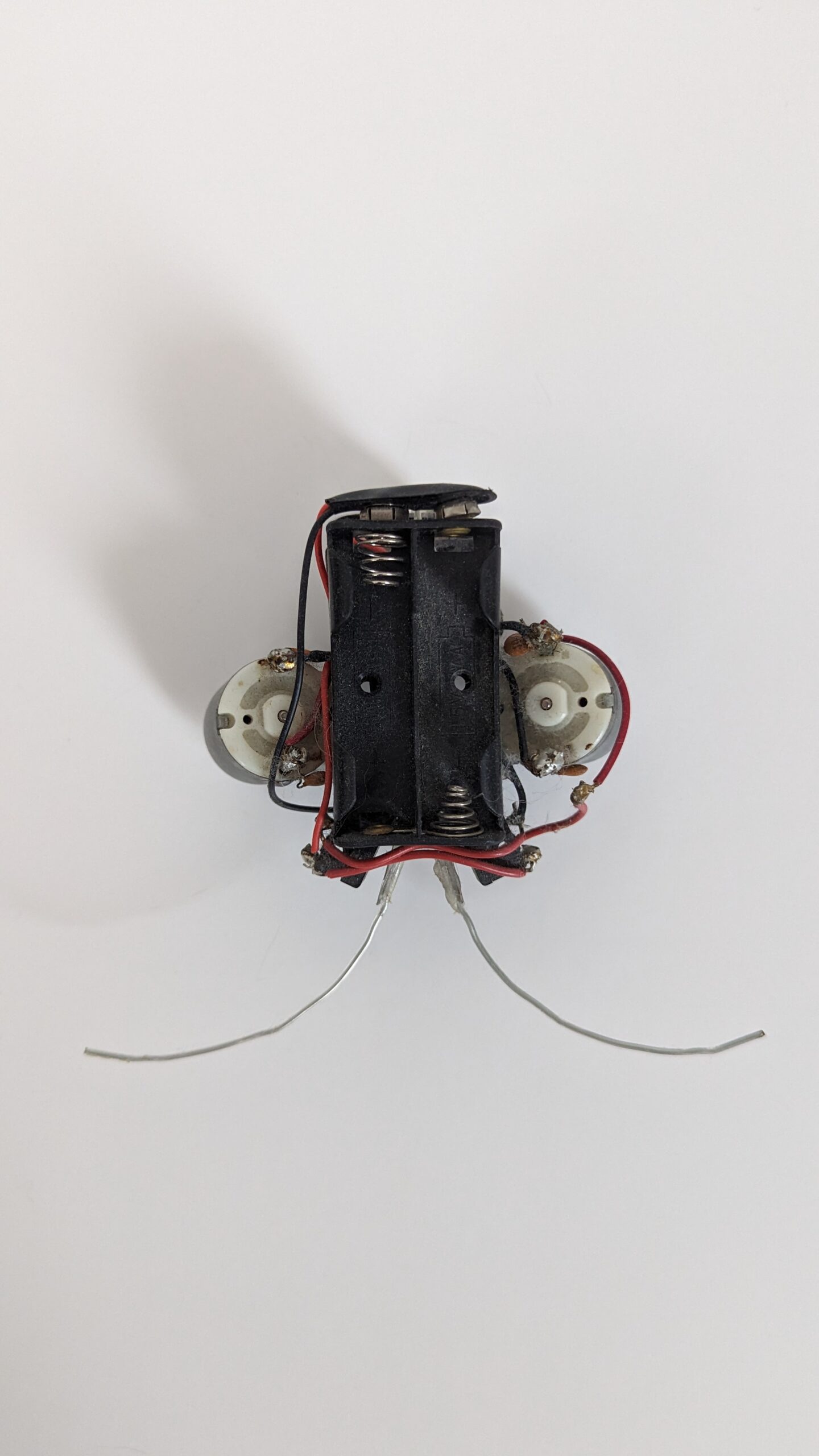
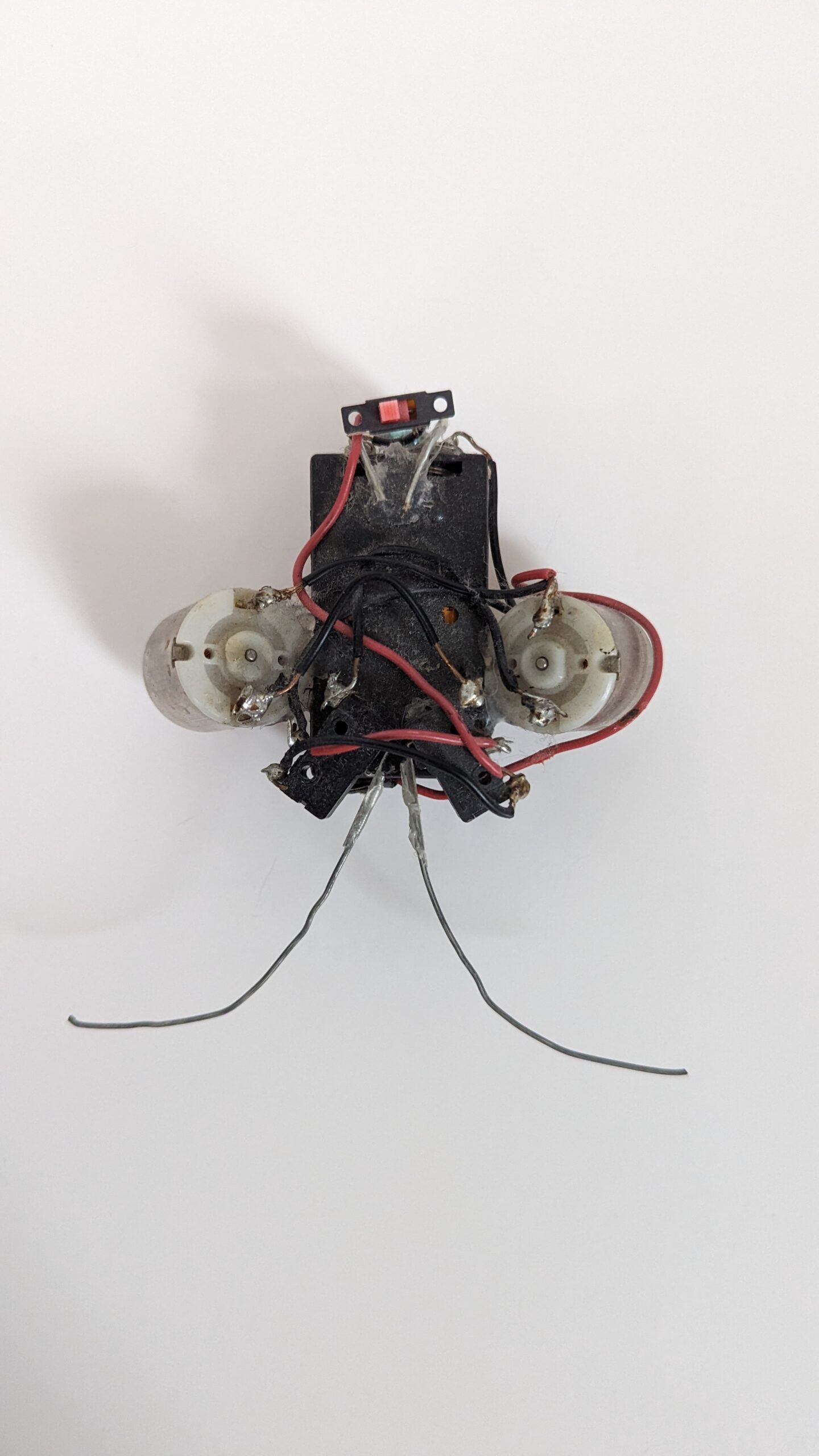
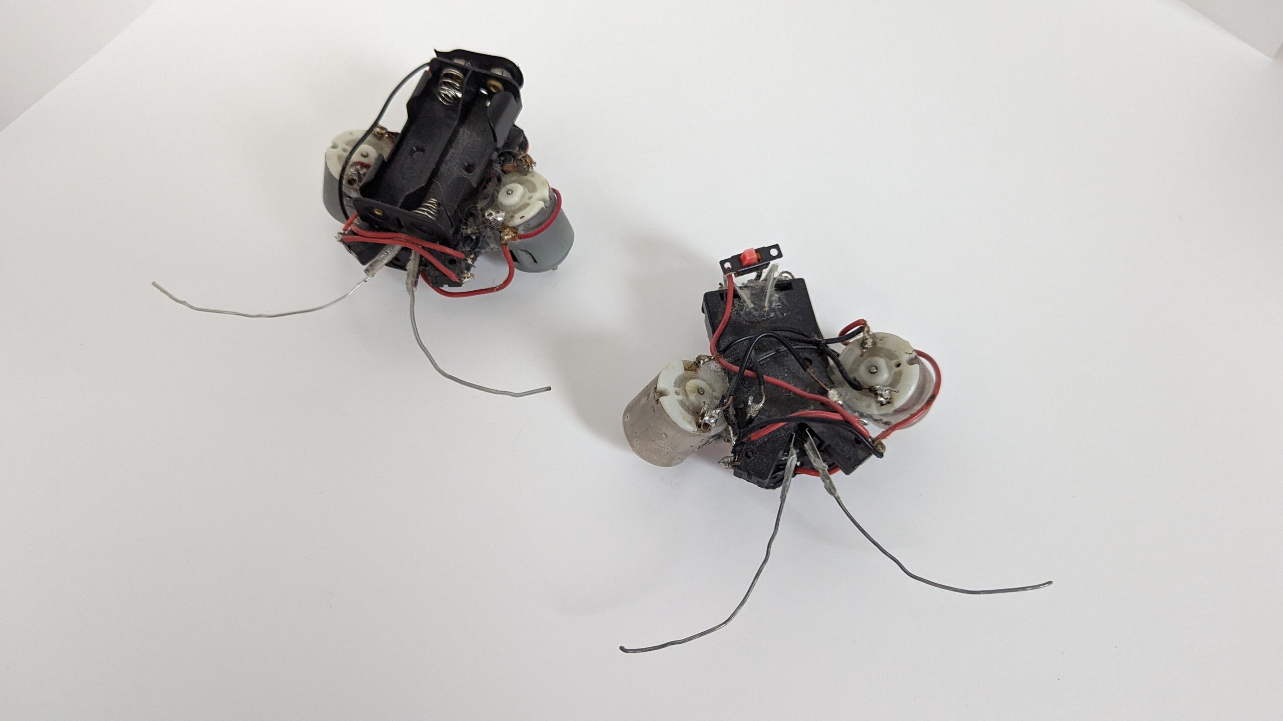
Beetle robots ~ On the left is one following the instructions but adding a power switch. On the right, I added a second battery pack to give it more energy and heft (to better press the tactile sensors).
Beetle Schematic with optional power switch. Base design uses single AA battery for each cell. Additional current can be had by doubling the batteries up in parallel. Double voltage achieved by wiring two AAs in series for BT1 and BT2.
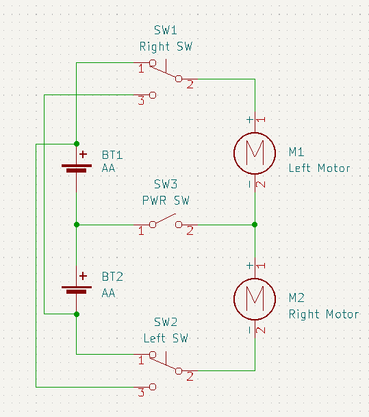
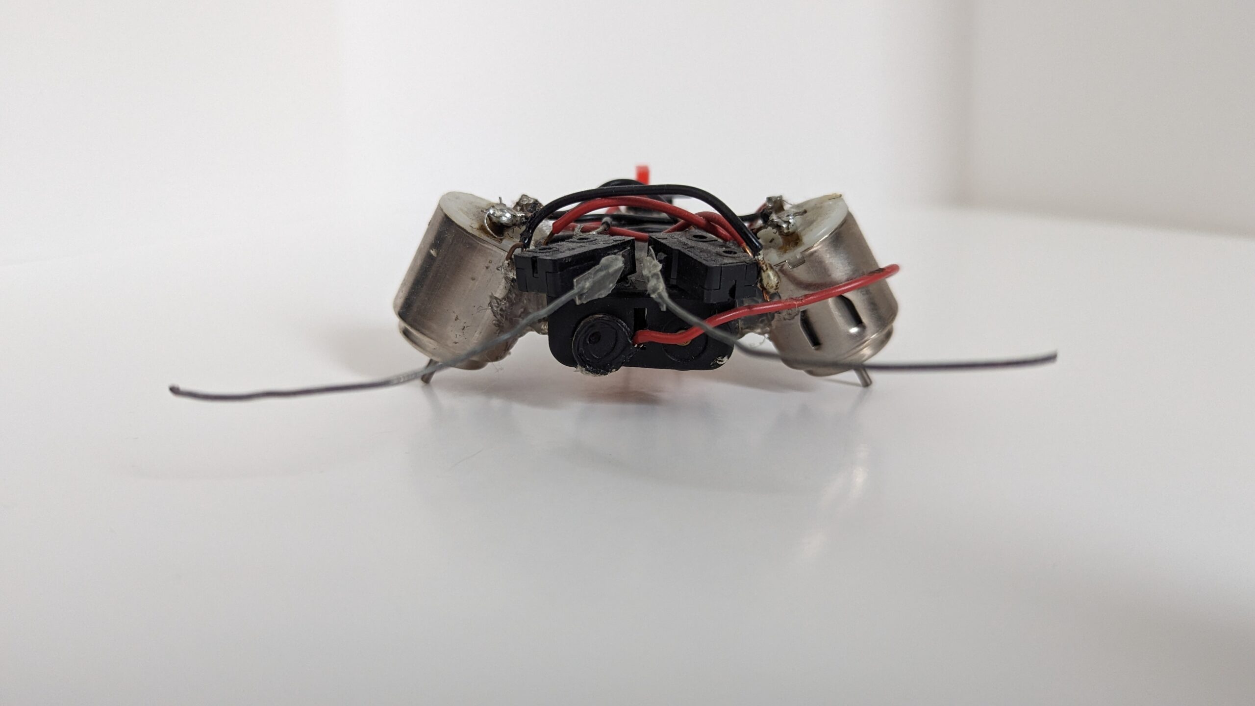
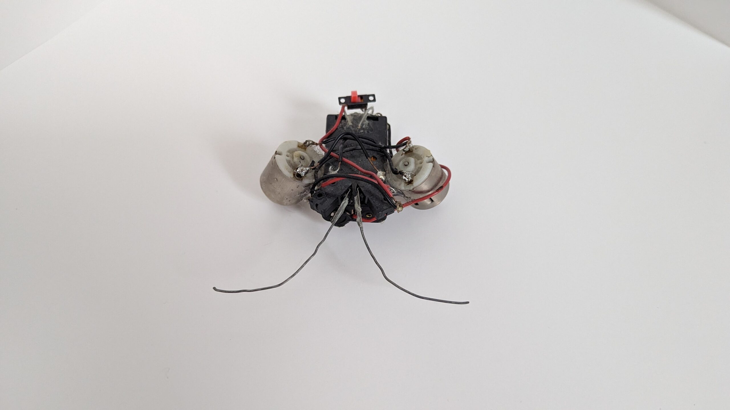
The trick with the circuit (that isn’t really clear in the schematic) is the proper orientation of the motors. When the both switches are not pressed the left motor should turn clock-wise and the right motor should turn counter-clockwise. Additionally, the whiskers need to be crossed-over such that, for example, when the right whisker switch detects an object, it needs to direct the left motor to spin in reverse. This will turn the robot away from the object.
All electronic components (battery box, switches, wire, etc.) were sourced from Radio Shack (RIP). The motors on my first beetle were salvaged from an old Hot Wheels toy. The motors on the second were sourced from Radio Shack. The paperclips used for whiskers were found lying around my parents desk. As will be a common theme, I used copious hot glue to hold the robot together.
Reflecting back, this robot is a particularly good design for younger kids. The circuit is quite simple, yet offers some good initial insight into behavior generation and sensor feedback. Additionally, it provided a decent soldering exercise. I also found Jerome’s second version of this beetle here. He has made several improvements. The whiskers in particular are a much better design.
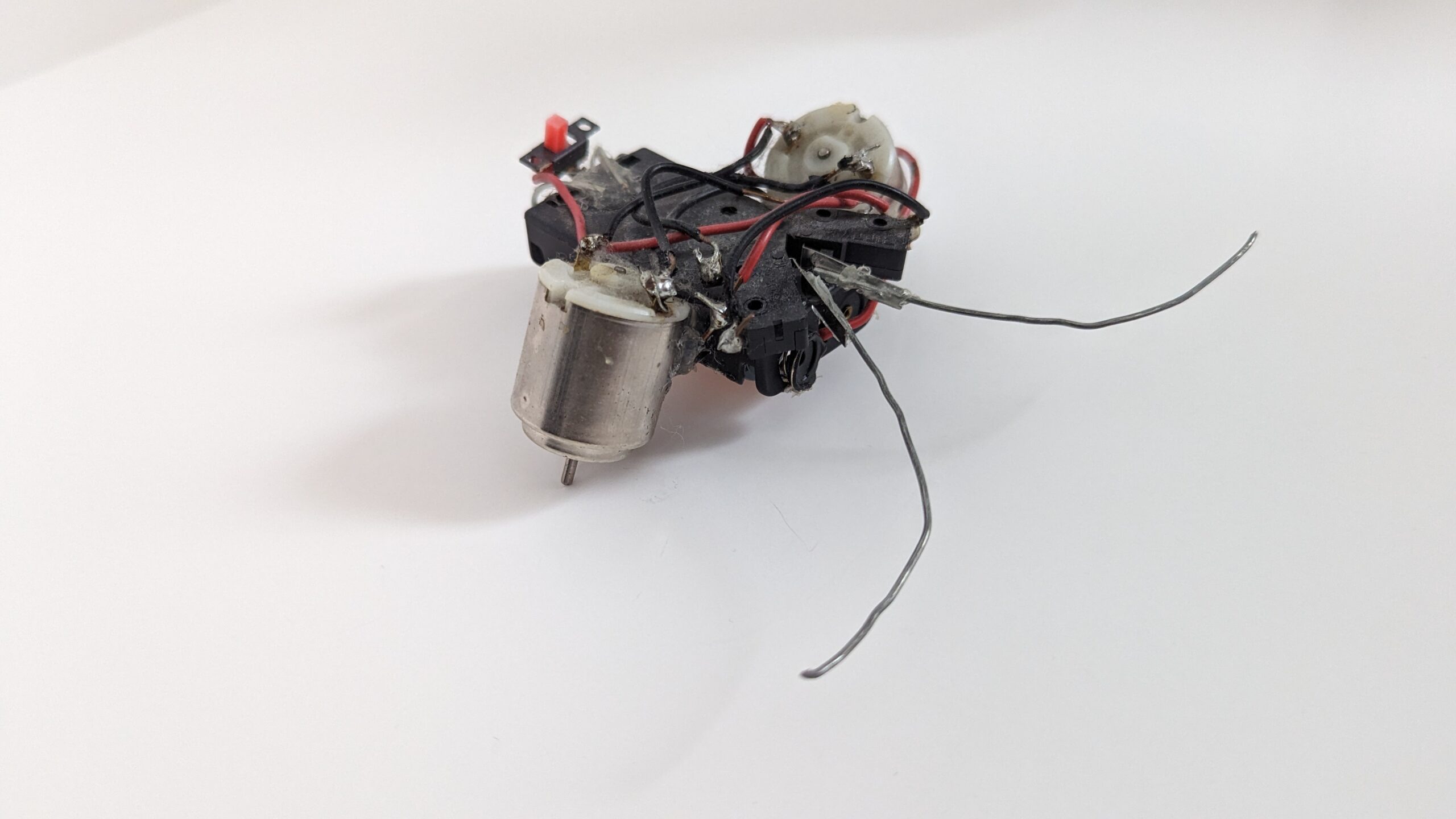
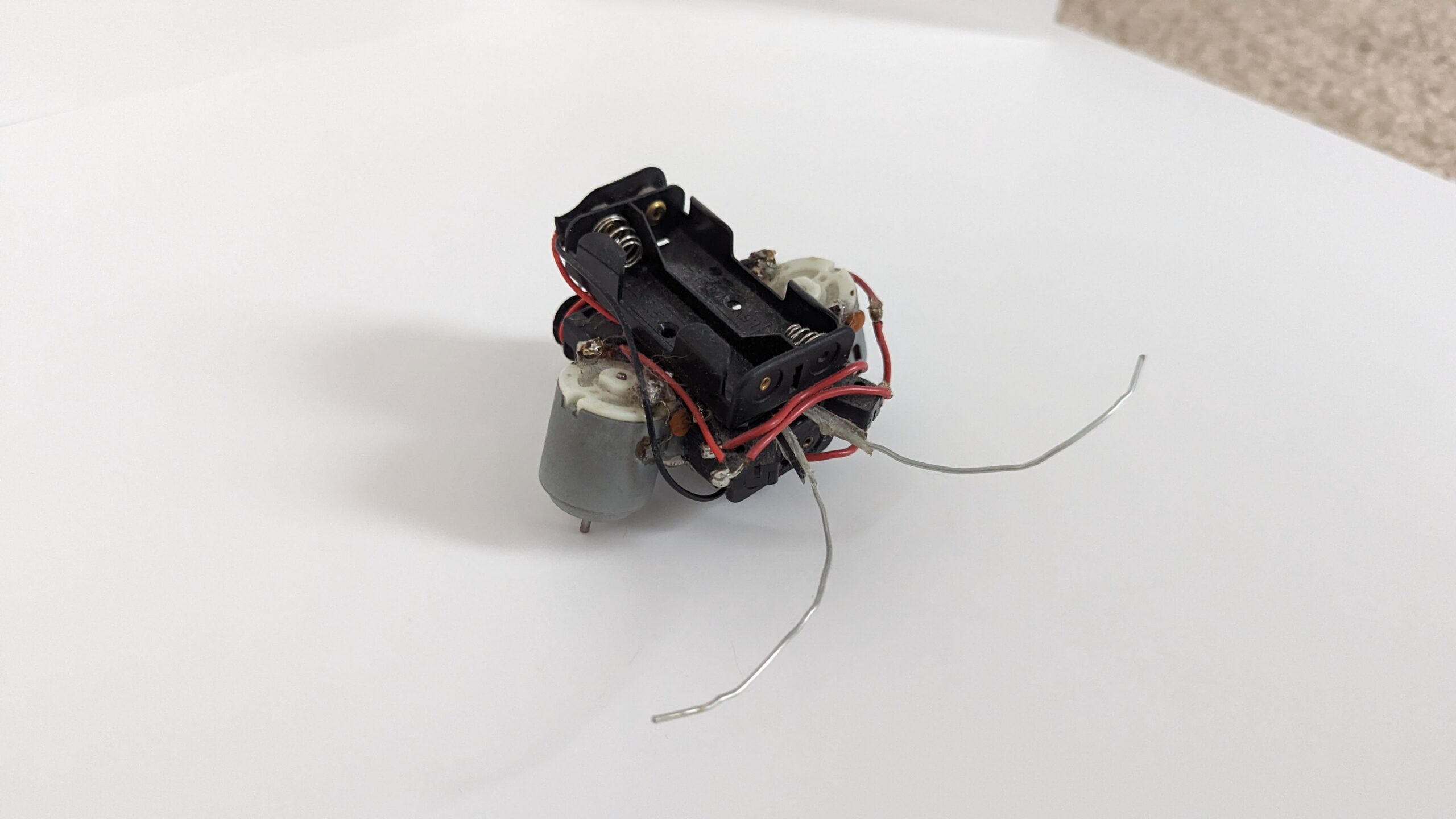
Some additional photographs of beetle bots:
Solar Robots
Symet
The next robot that I built was inspired directly by BEAM robotics. Following instructions from the book Junkbots, Bugbots, and Bots on Wheels, by David Hrynkiw and Mark Tilden, I designed and salvaged components for my Symet (specifically a Trimet due to the three capacitors).
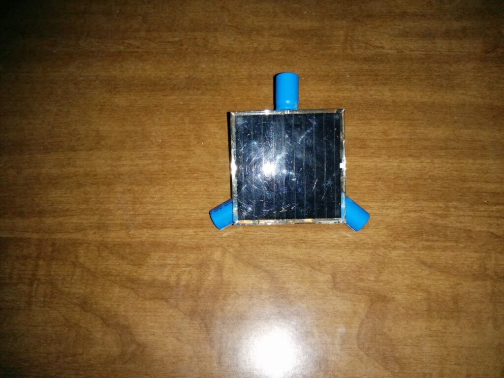
Symet ~ A solar robot consisting of a simple FLED solar engine driving a single motor.
A Symet’s purpose is to convert solar energy into periodic movement. It has been described as a “robotic plant” At its core its a solar engine hooked up to a motor. The solar engine itself isn’t particularly special, it is a simple circuit that monitors the capacitors and when sufficient energy is stored it will power the load; thereby draining the capacitors and restarting the cycle. When our load, the motor, moves it pushes the robot slightly. Based on the configuration of the capacitors, this produces an arc movement across the floor. The genius of the Symet’s design is that if it is tilted onto on of its other sides it will continue to move, undeterred.
Schematic for Symet (and FLED solar engines generally).
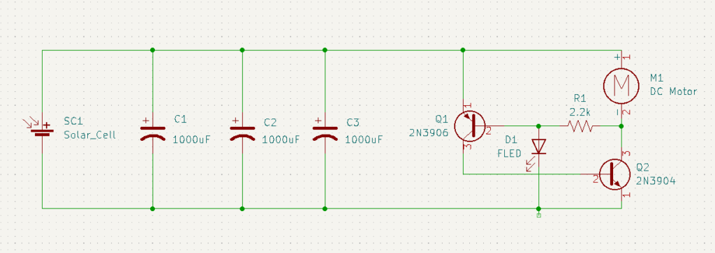
The solar engine that I used (as discussed in the book) was a FLED engine. A FLED or Flashing LED is an integrated circuit that blinks an internal LED. The through hole form factor is the same as a normal LED. However, the integrated circuit cannot turn on until the capacitors charge to a certain voltage. Until the FLED fires, the voltage across the motor is zero; it floats up to the capacitor voltage. Once fired, it draws current and drops voltage across the motor triggering the 2N3906 and 2N3904 transistors. With both transistors on, the motor is now near directly tied between the voltage and ground power rails.
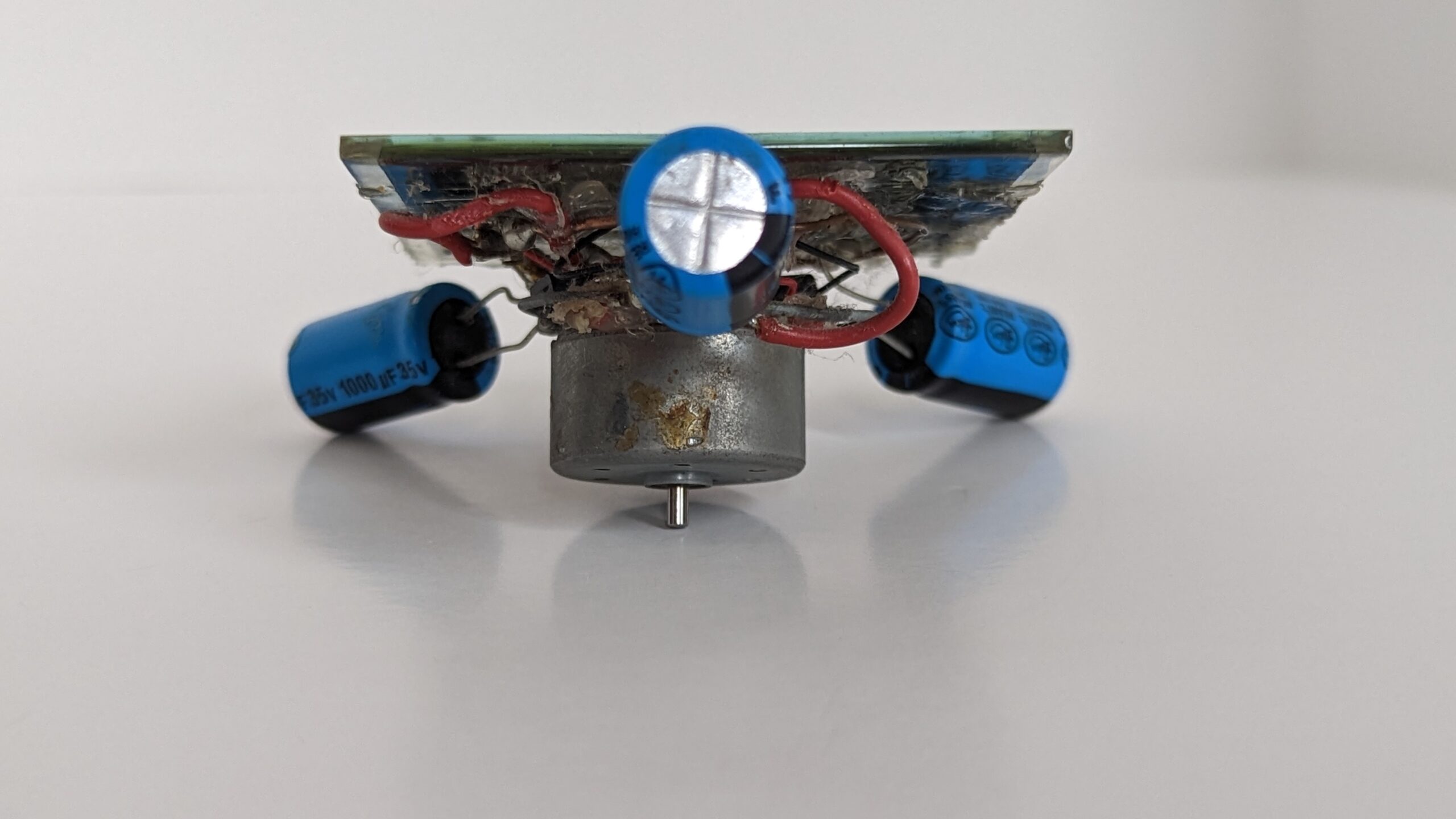
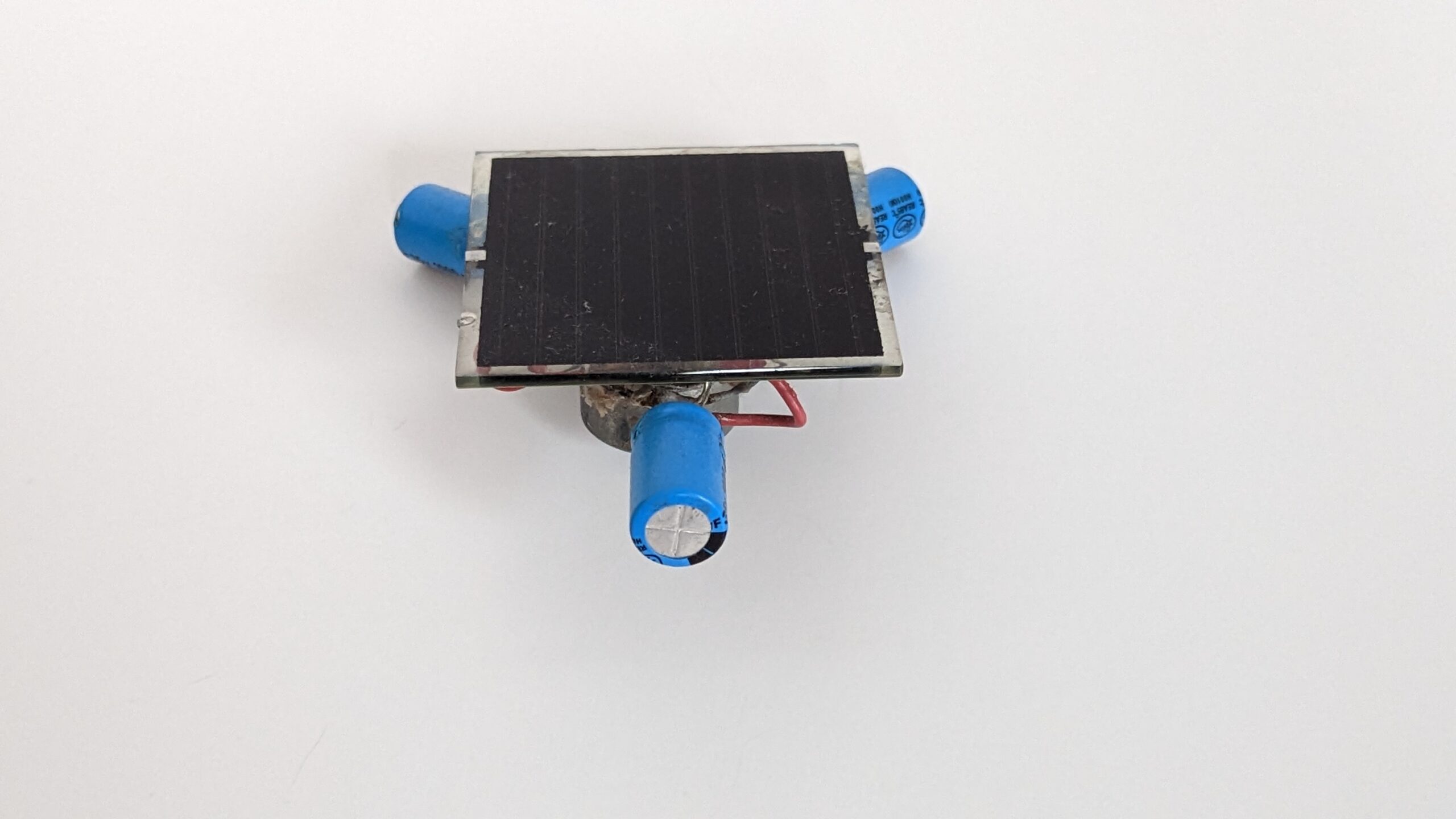
I went with a three capacitor design for aesthetic reasons (though there doesn’t seem to be hard-and-fast rules for how many capacitors a symet should have). To start the circuit, I soldered the capacitors to two rings, which became my power and ground rails. I then free-formed the solar engine in between the rings, soldered in the motor, and finally connected the solar cell. The result is what you saw above.
For this robot, I salvaged the motor from an old CD player. The key to building a Symet is to find a motor that has a wide diameter but isn’t very long. I sourced the solar panel from American Science and Surplus. Unfortunately, it has been a long time since I have seen this particular solar cell listed. All other electronics (FLED, capacitors, transistors, etc.) were sourced from Radio Shack.
As a final note, the solar cell used needs to produce a fairly high voltage at ambient light levels to trigger the FLED. I would aim for a cell that has a peak of 4.5V or 5V. Of course you also want to have decent current so that you aren’t waiting 15 minutes for a small twitch of the motor.
Some additional photographs of Symet:
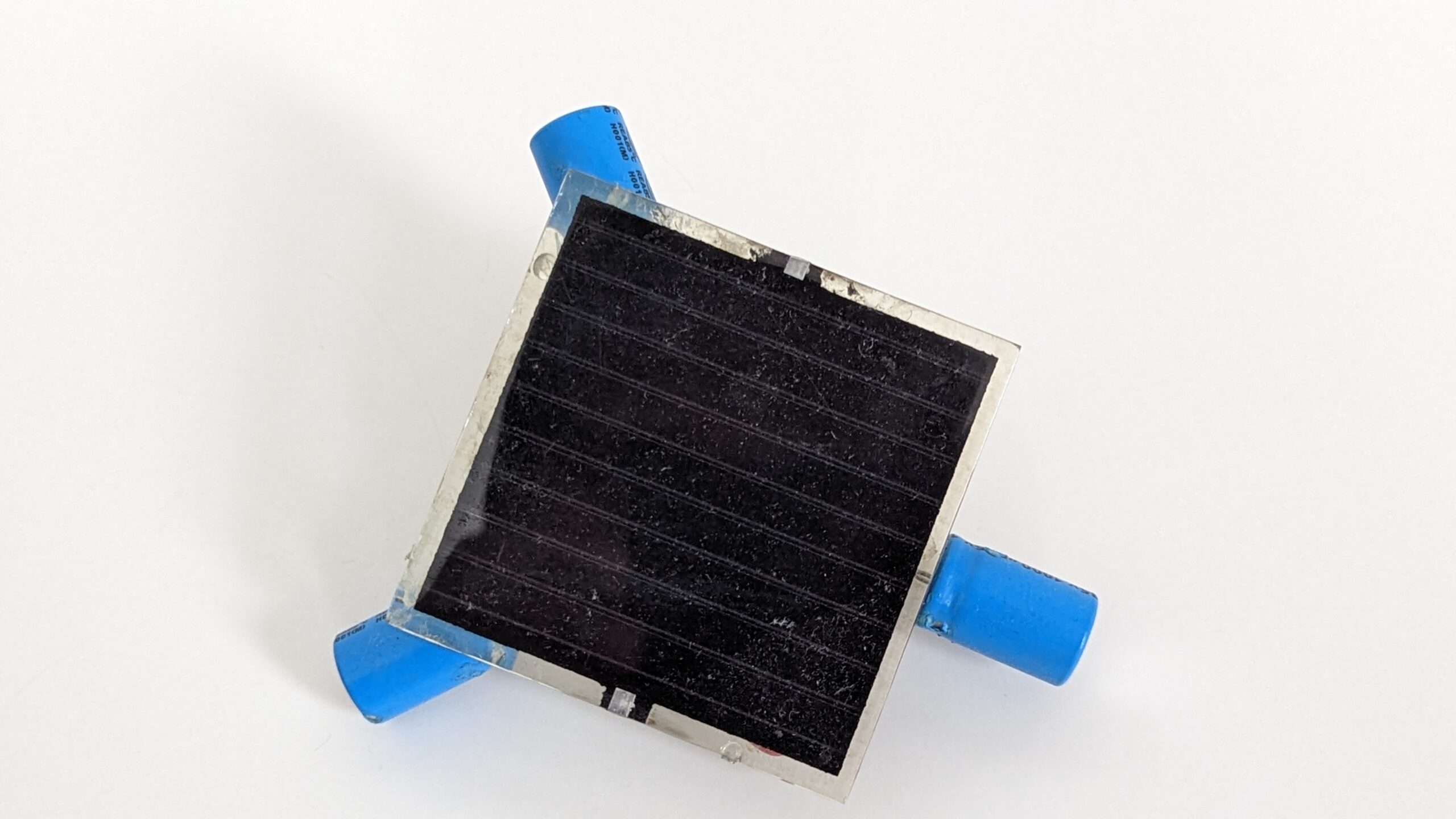


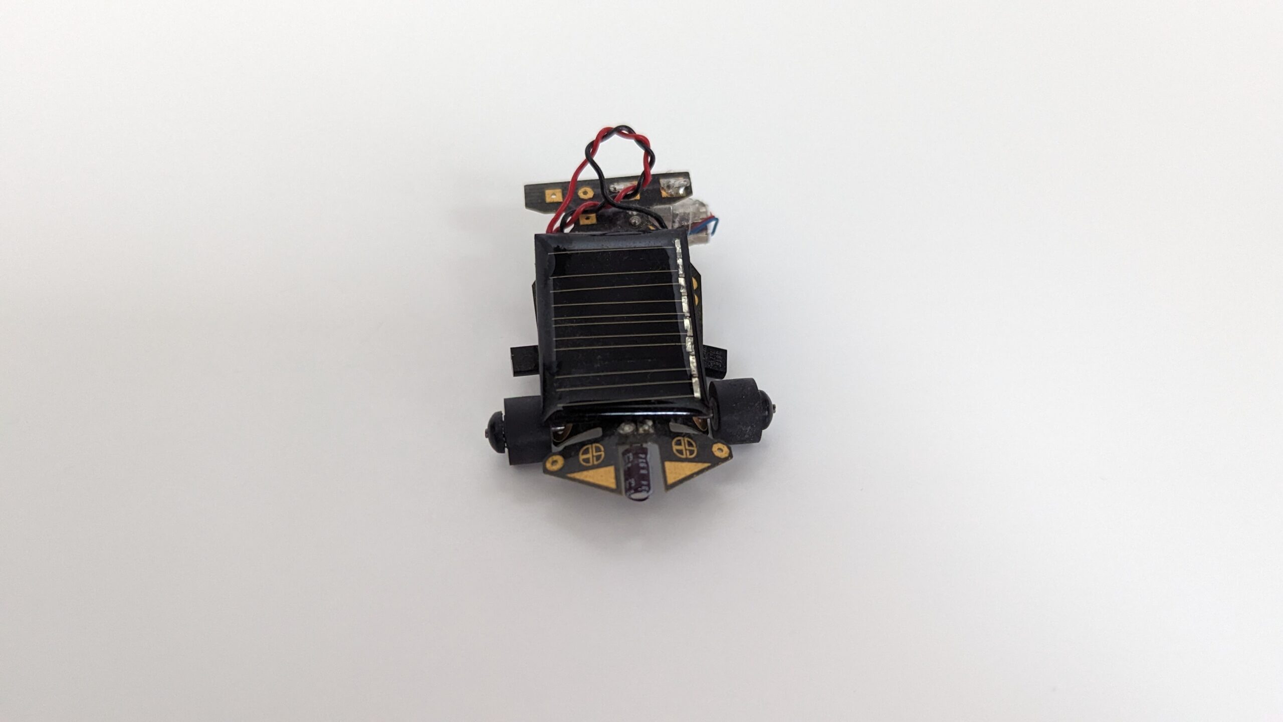
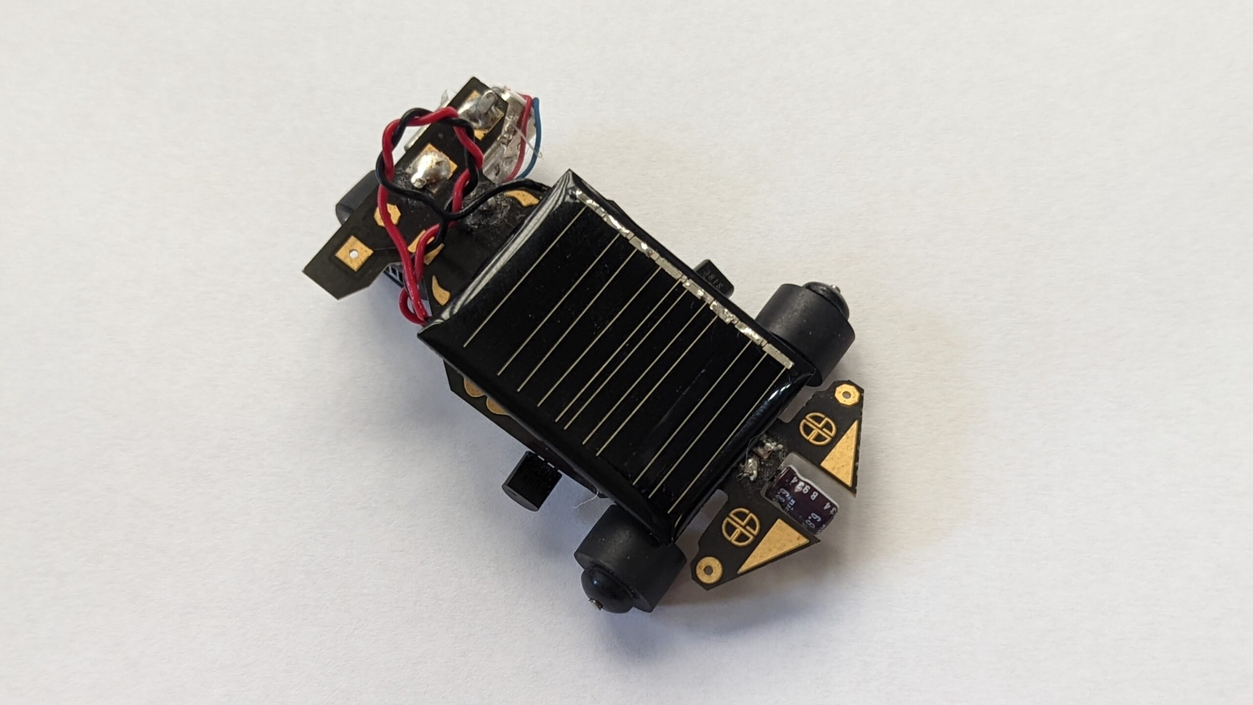
Solar Roller
My second solar robot was a kit from Solarbotics. Solarbotics was the go-to place to purchase BEAM robot components and kits. They have since branched out to other robotics and electronics projects. The one challenge I had living in the United States is the additional customs time associated with shipping from Canada. Alternatively, I think if you buy the kit from a US store like Robotshop then shipping might be faster?
While building this robot, I dropped the rear wheel under the workbench. After searching for what seemed like an eternity (but was in actuality probably ten minutes), I gave up and swapped in a small LEGO wheel. Unfortunately this change made the robot curve a bit during its run.
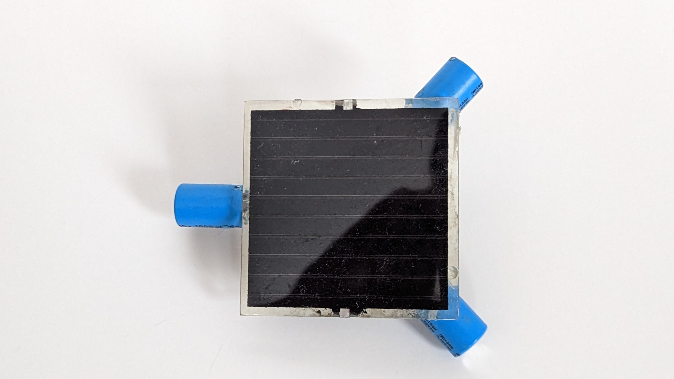
Overall the on-time when the solar engine activates is nice and long. It does take a few minutes of direct sun (in Wisconsin) to get the robot to move though. As for the construction, the build went together easily and the instructions were simple. The solar cell itself was pretty cool as its a lot smaller than Symet’s. If you don’t feel like free-forming a robot then this is probably a good kit to get started in BEAM.
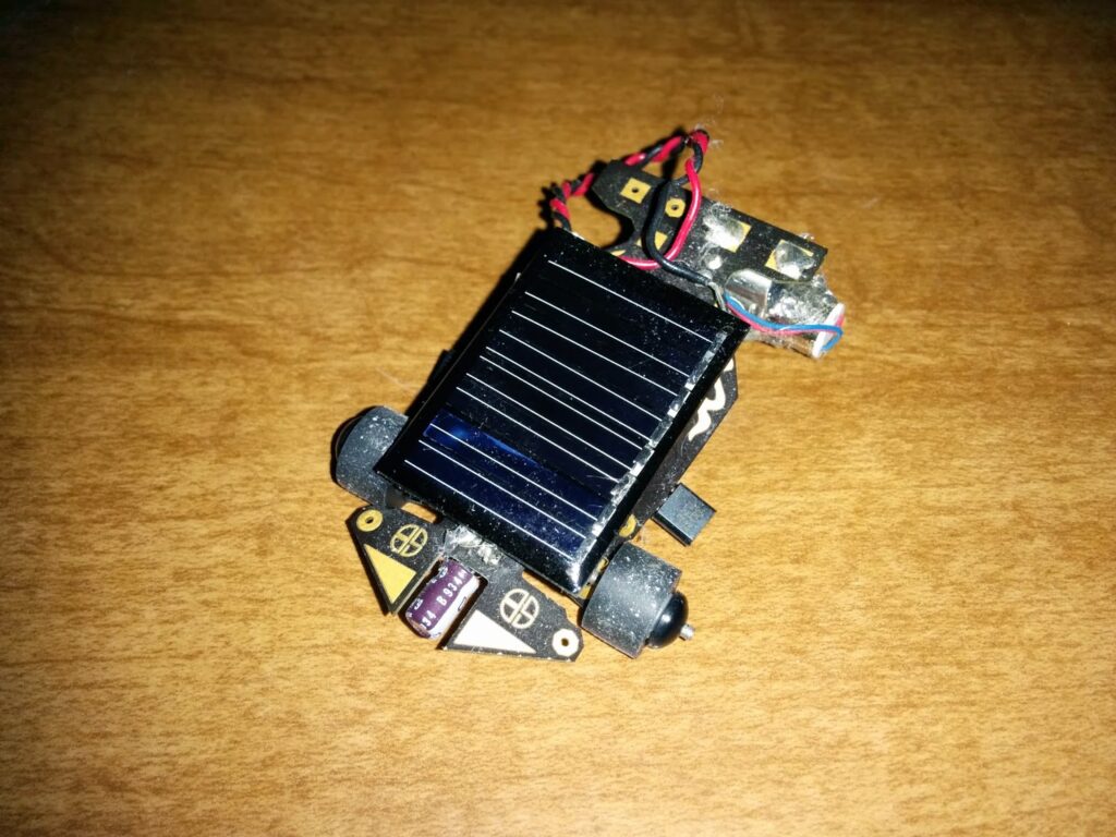
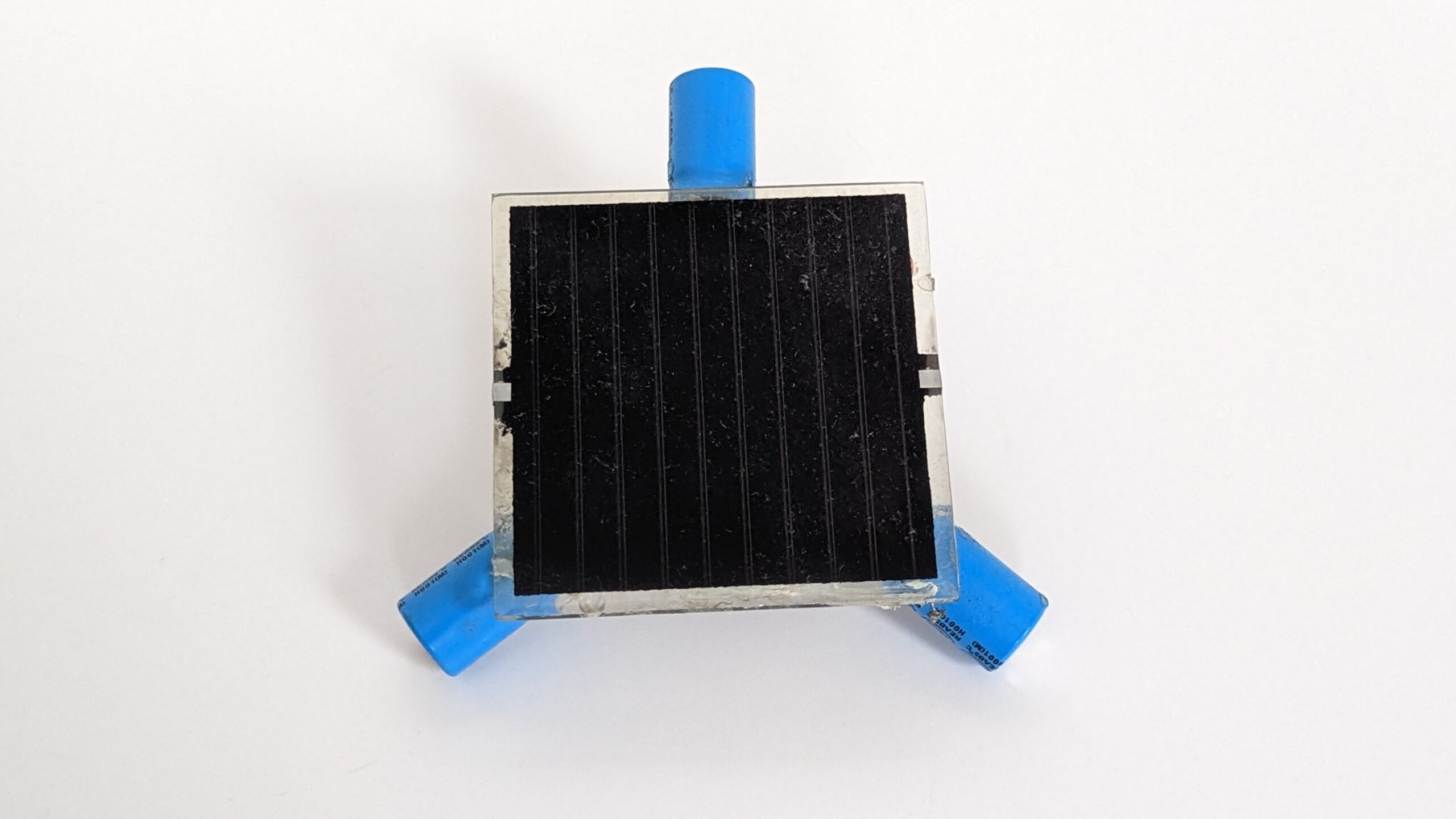
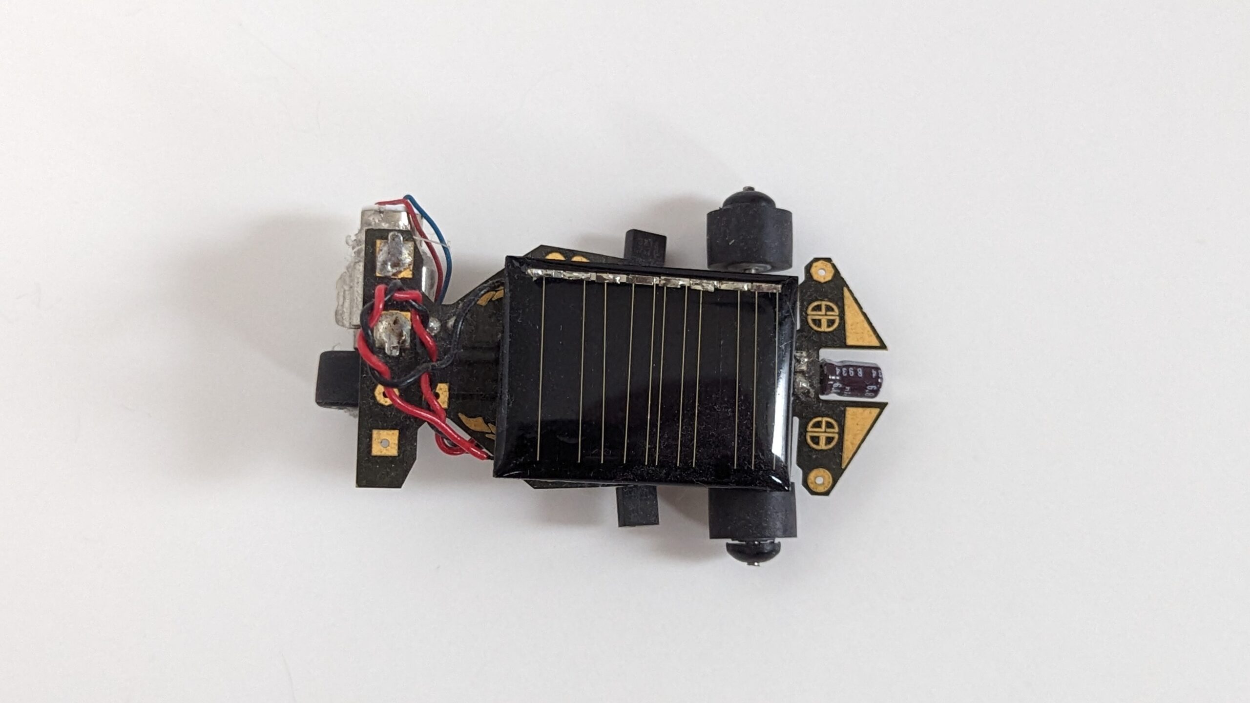
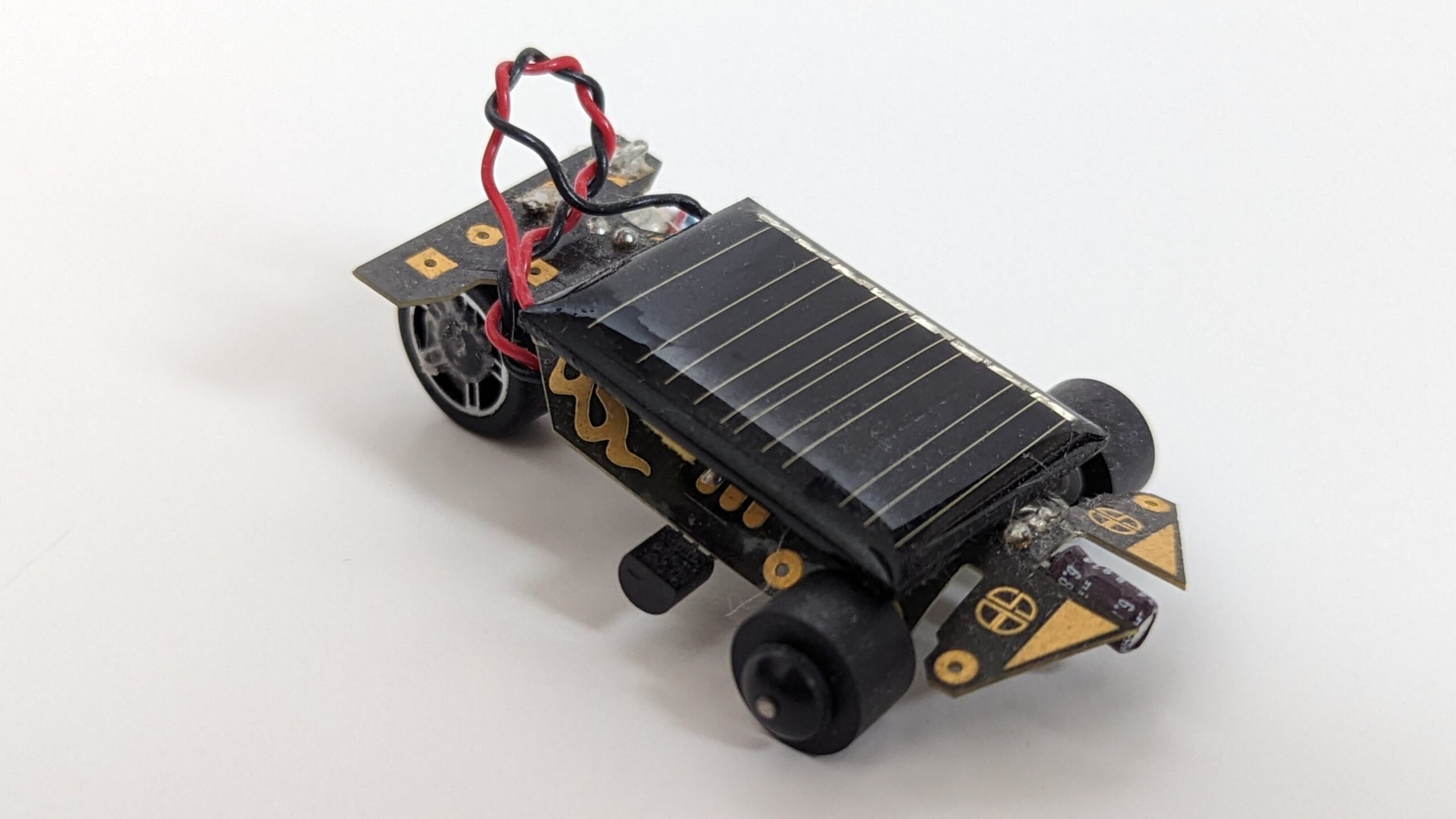
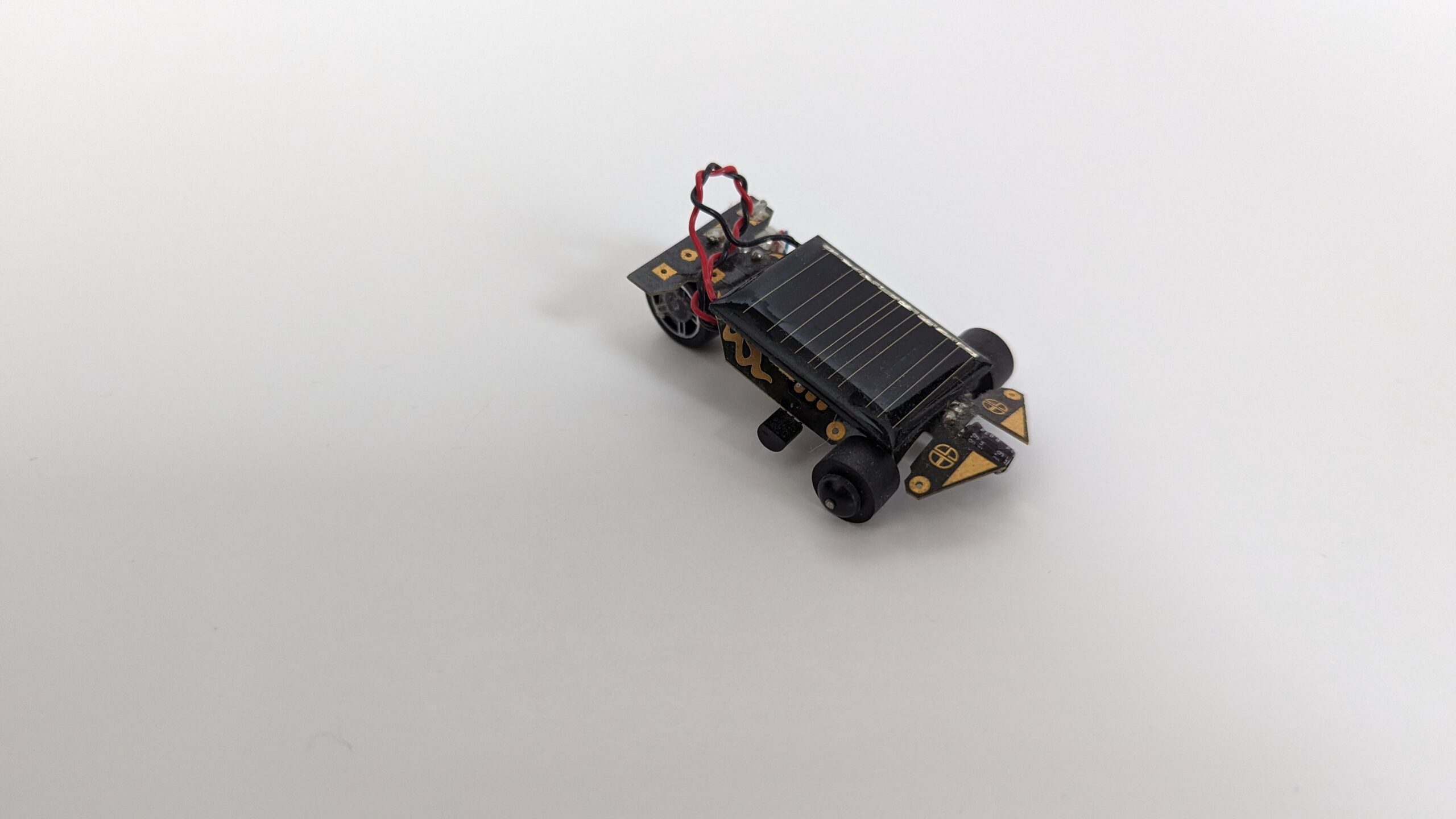
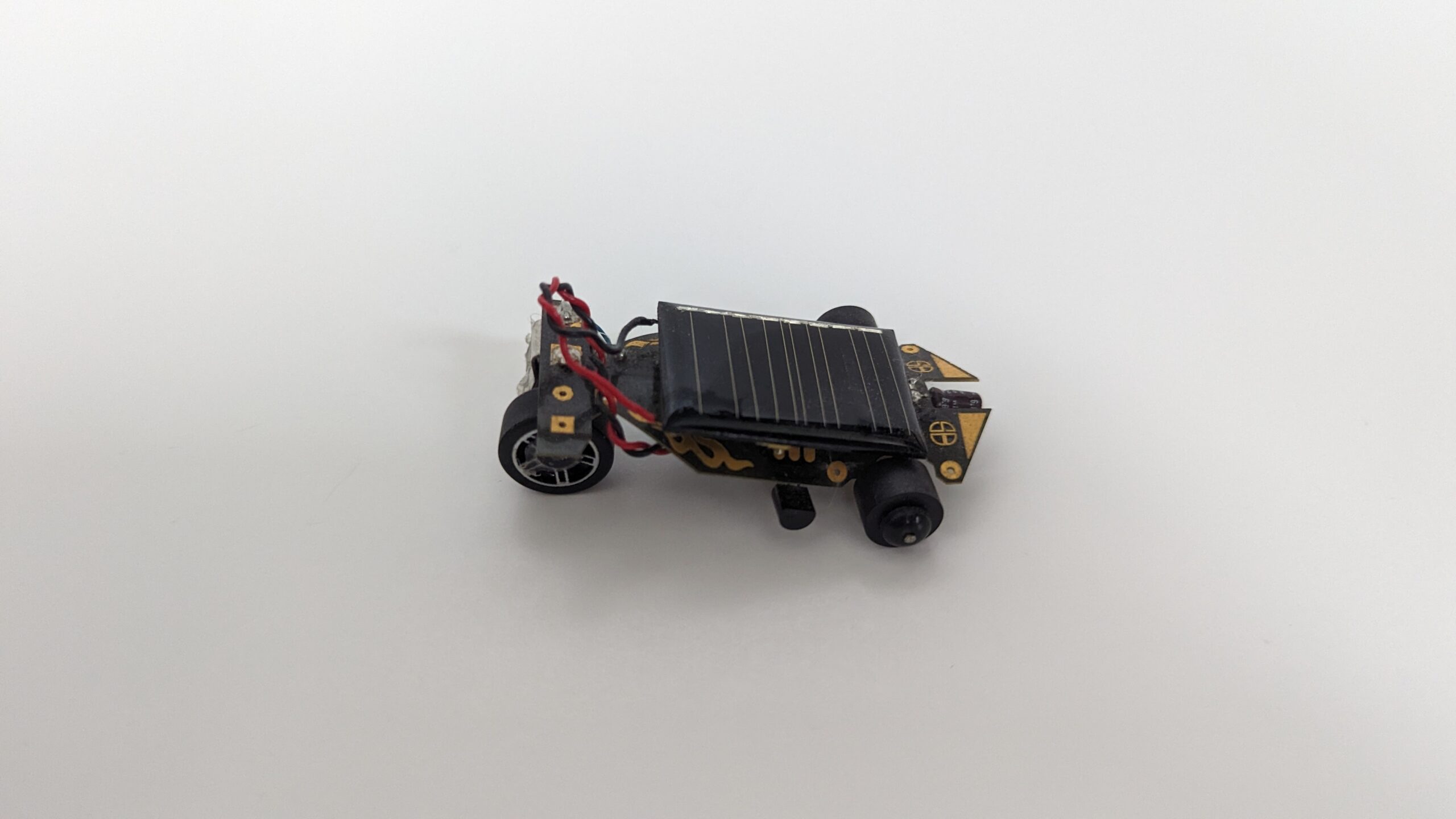
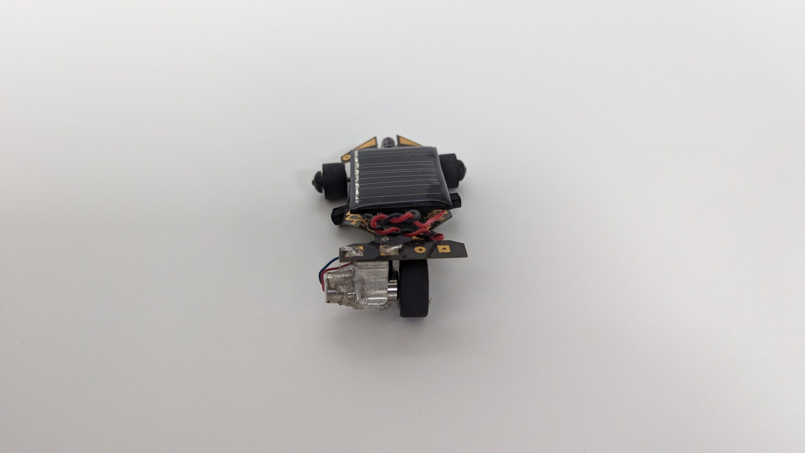
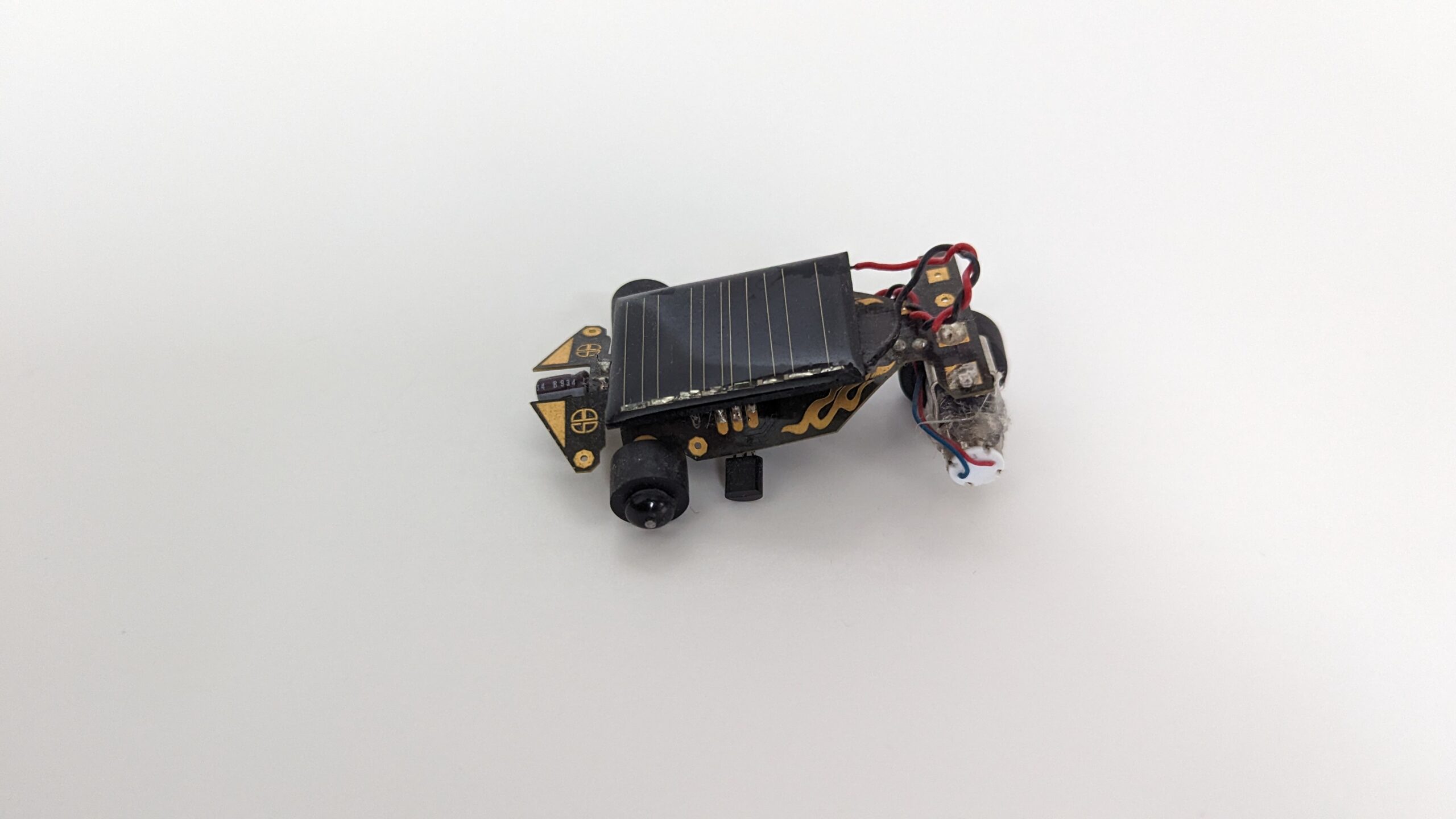
Solar Roller ~ A Solarbotics kit that requires a bit of “easy” soldering.
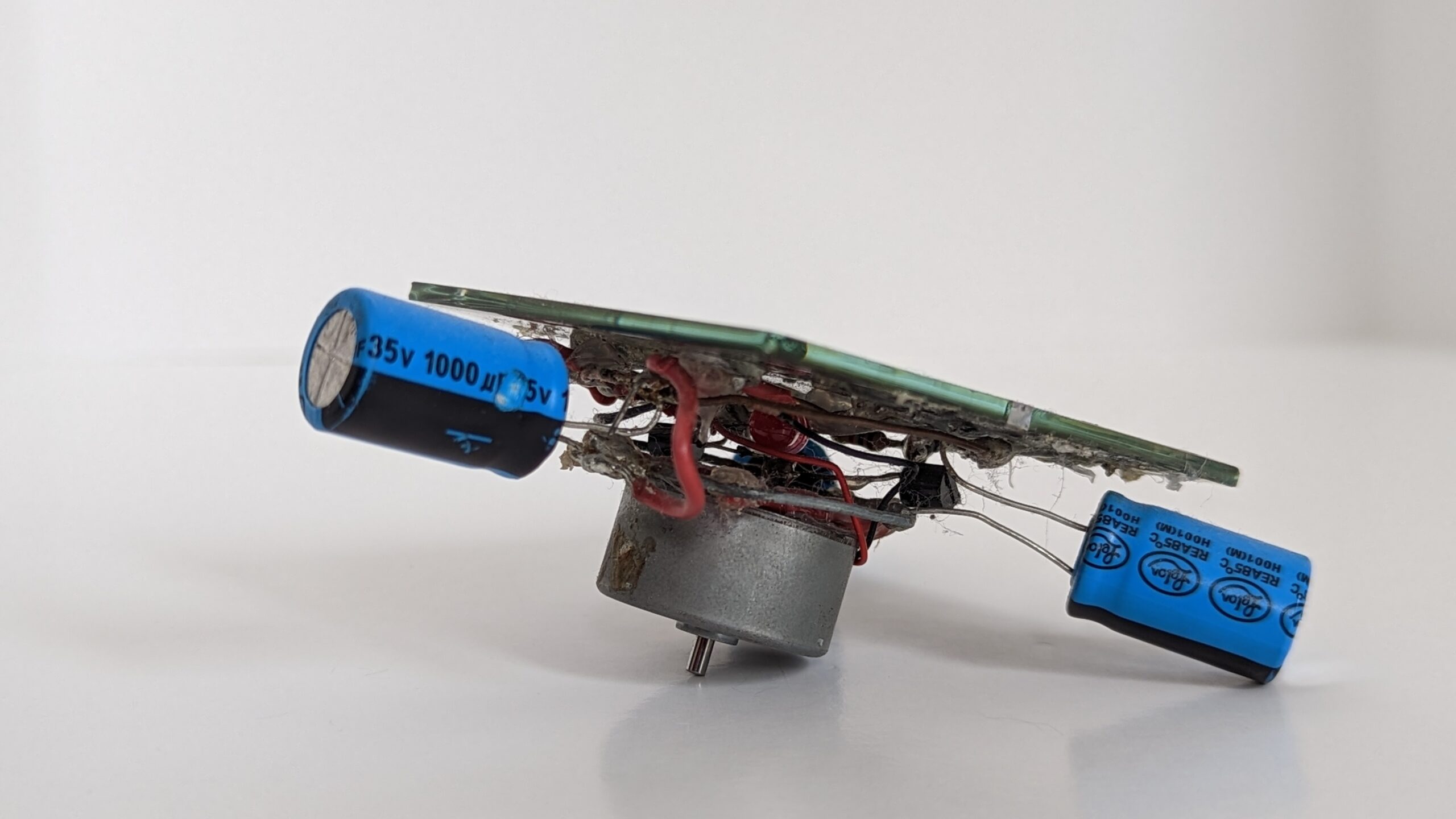
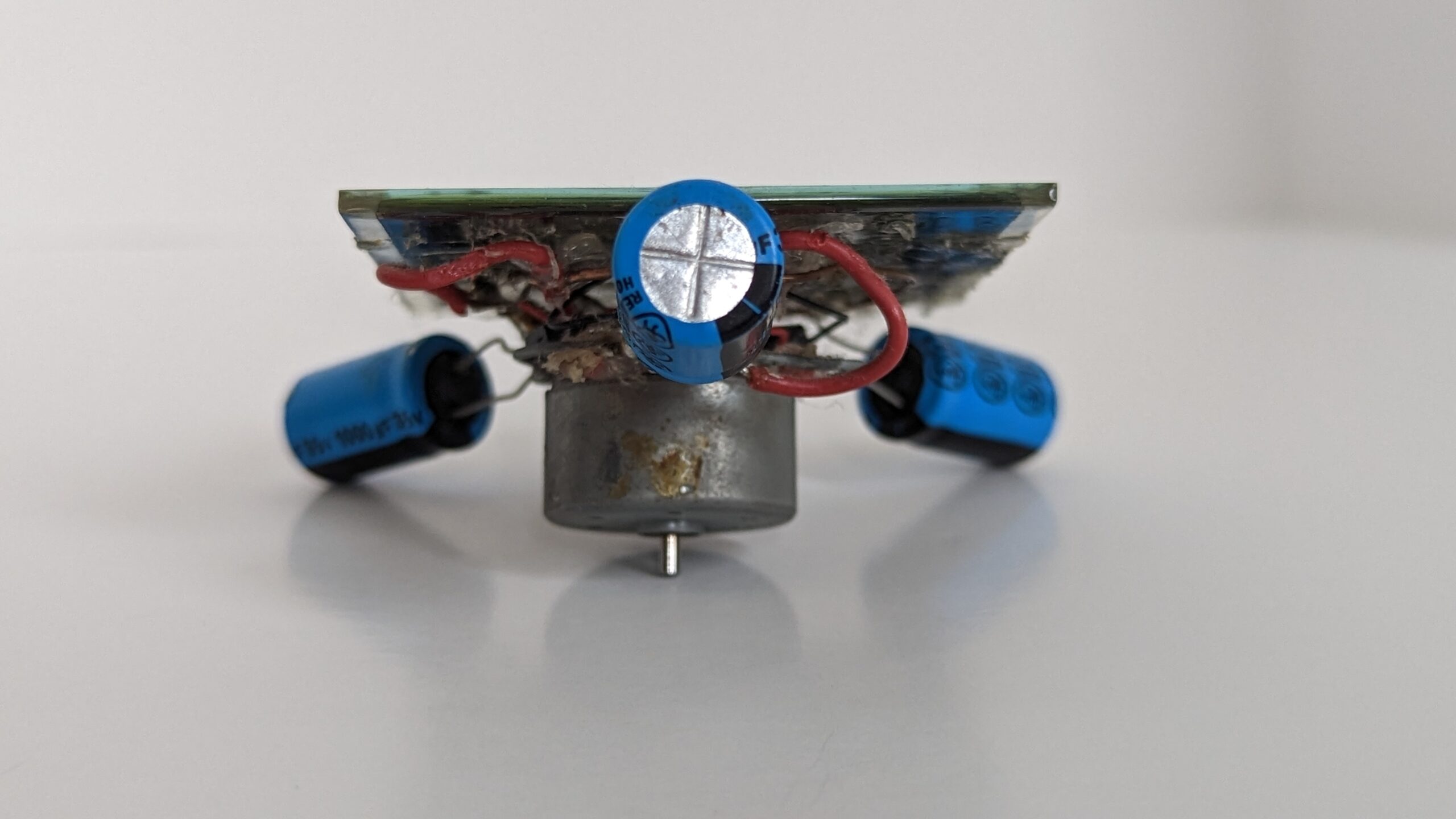
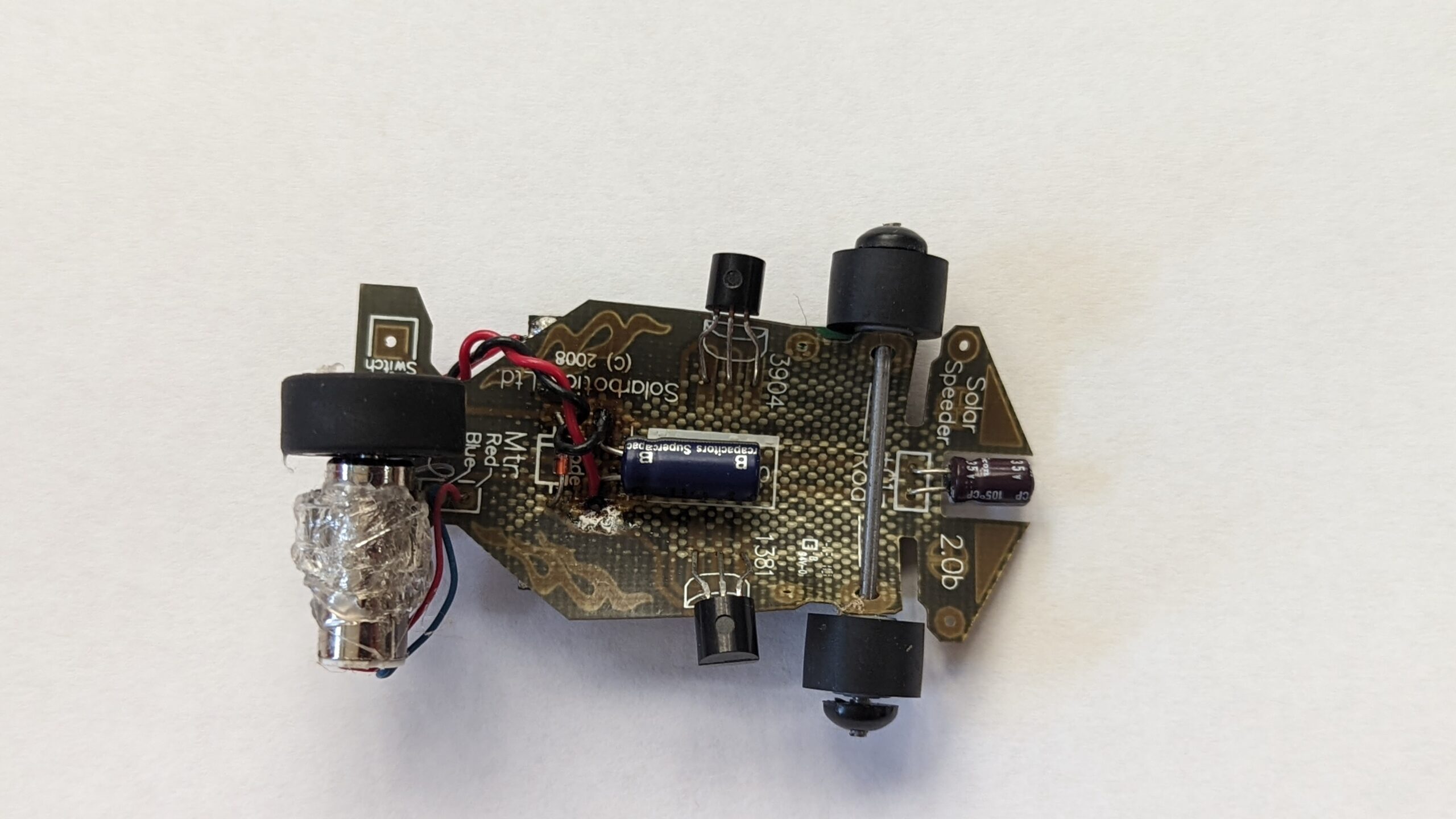
Since restarting the blog (and reworking my old robots), I noticed the solar roller’s large 0.35uF capacitor has leaked its electrolytic fluid. Sadly, solar roller hasn’t been out in the sun for years and its only recently that I discovered this. I guess a new chore project for me is to swap out the capacitor.
Solar Roller on its back with a dead capacitor (bright blue cylinder centered) leaking electrolytic fluid.
I am now on the hunt for a suitable replacement. Looking up the documentation on Solarbotics’ website, they list it as “0.35F 2.5V Gold Capacitor (SKU: CP0.35F)”. I probably want to keep the capacitance near that value. Though if I do change it, I will probably reduce it slightly so that I can get more action out of it. Its not like mine is ever going to compete for distance.
Fix Update: I replaced the old cap with a 220 mF capacitor from Digikey.
Some additional photographs of Solar Roller:
SymFlower
As a disclaimer, this robot is one that I have recently reworked. I will document the both the original and modified versions.
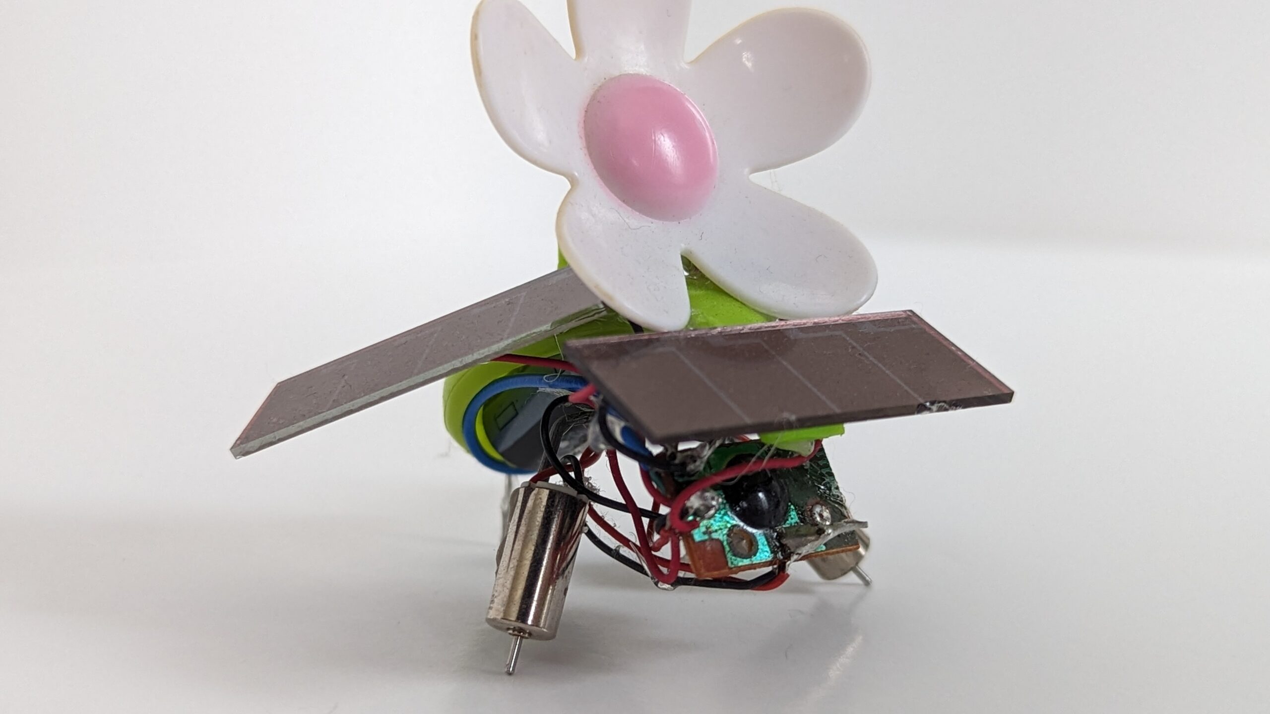
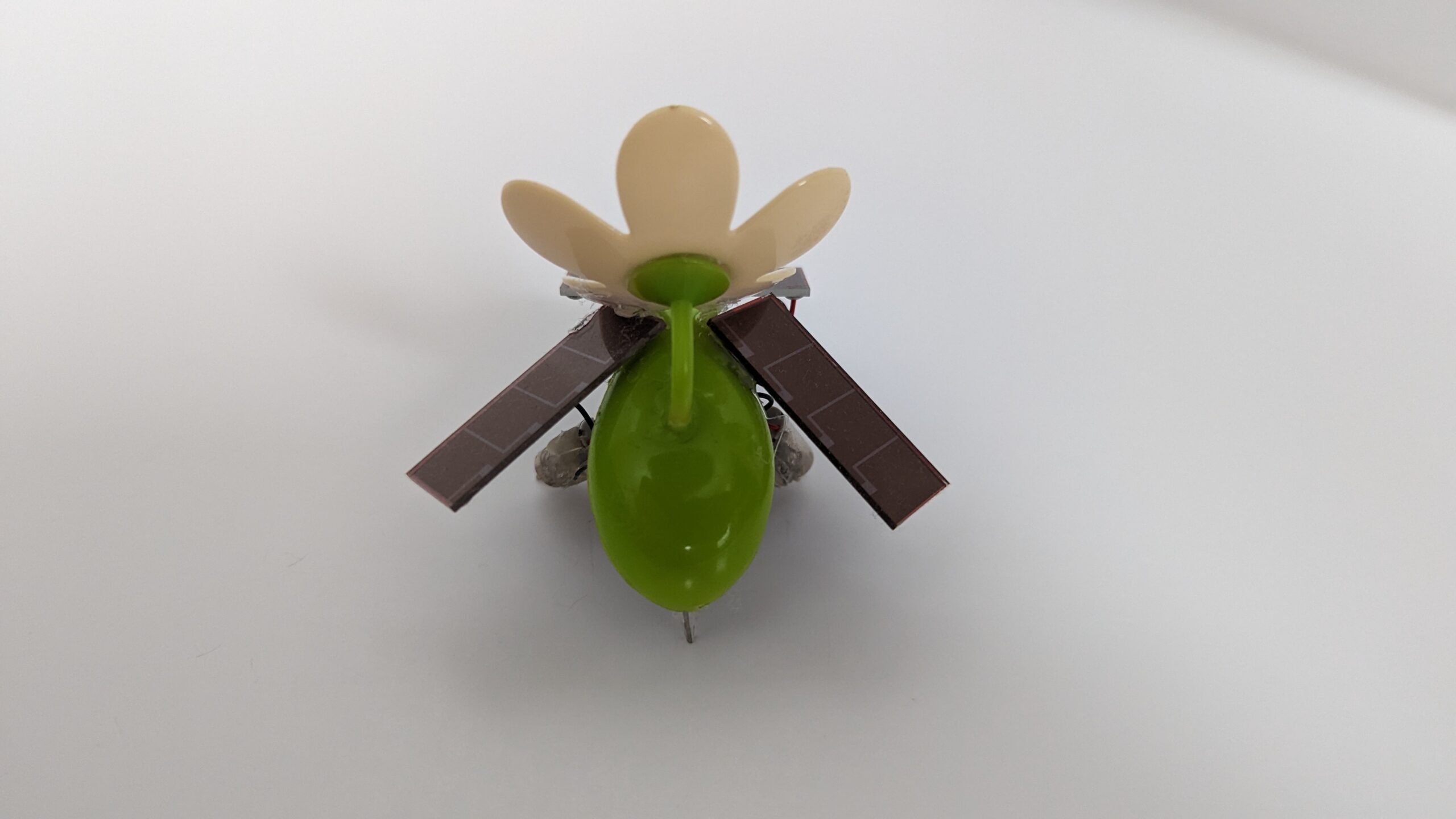
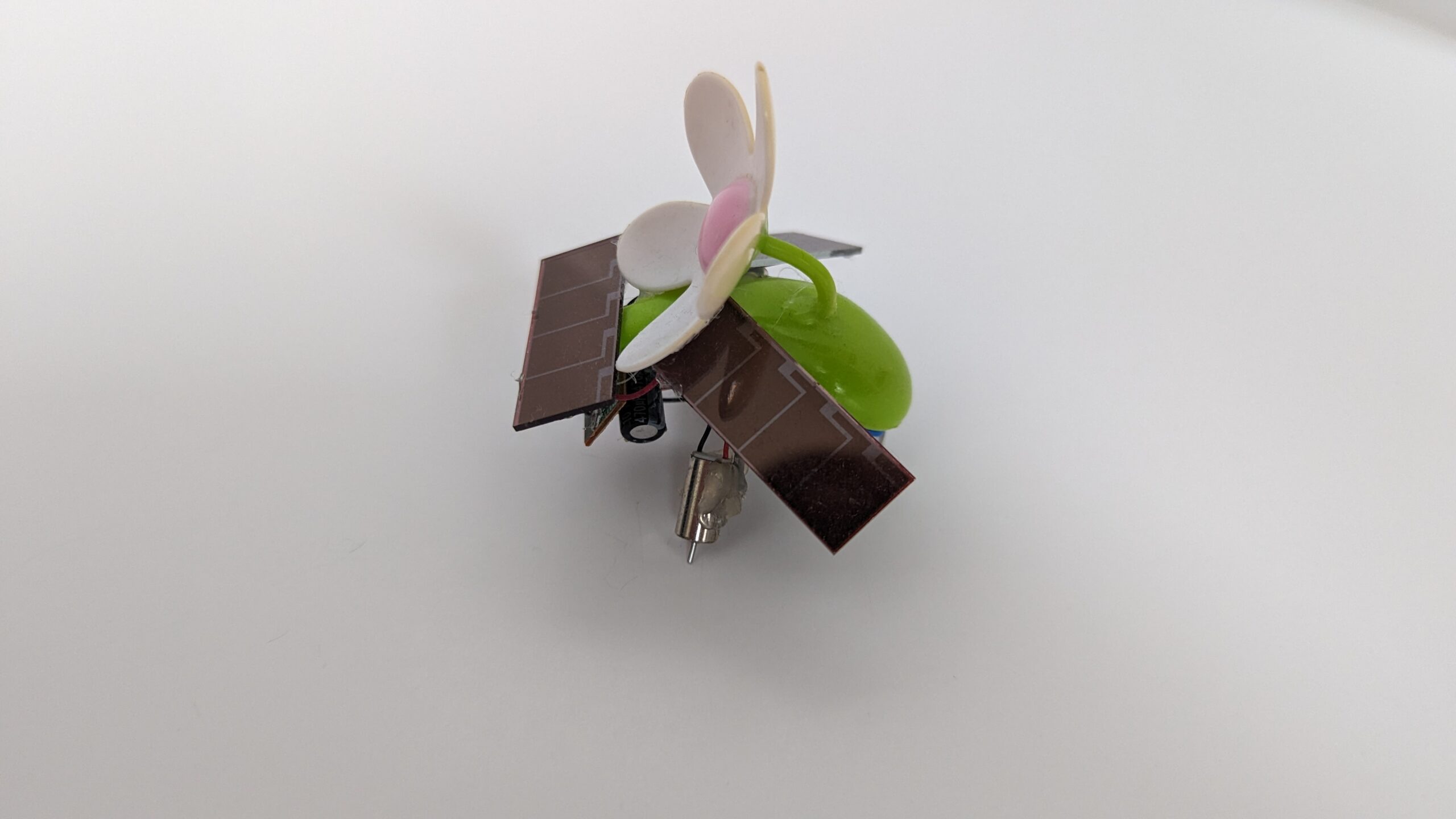
SymFlower is a little solar Symet-esc robot using parts salvaged from a solar plant decoration that my great grandmother had. The decoration would originally bob the flower left and right when exposed to sunlight. However, a plastic pin eventually fatigued causing the flower to stop moving. Instead of throwing away the decoration, I repurposed it as a BEAM robot. As the solar engine electronics were already functional, all I had to do was add some new motors, and additional capacitors.
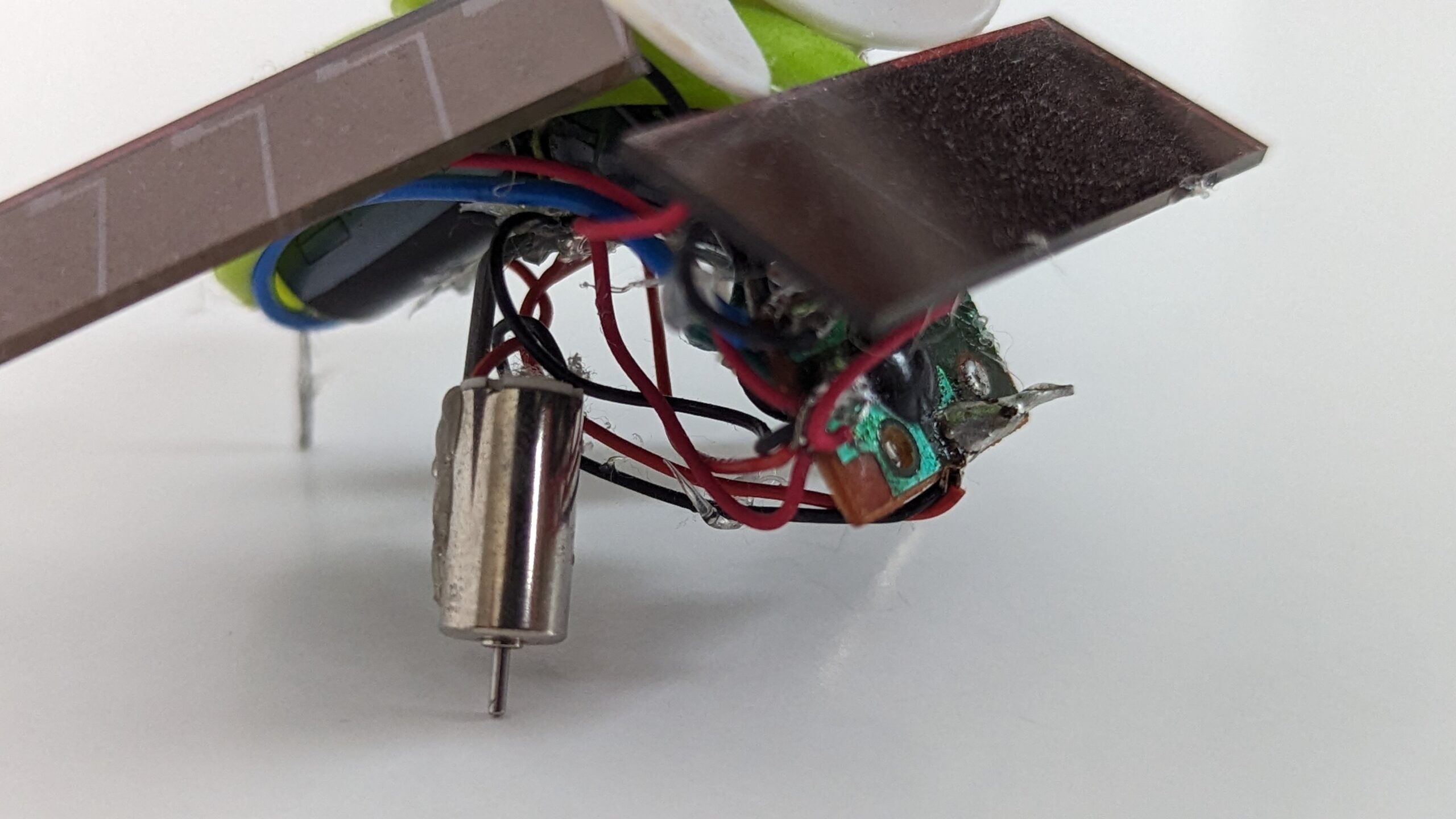
I ended up using one of the plastic leaves for the body and glued the flower on top. I attached the solar cell to the front. I added two motors to it to give it a bug-like appearance. The tail caster is a small piece of paperclip. I was able to fit two small capacitors in the thorax of the robot.
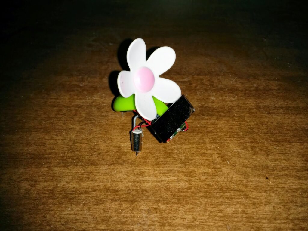
SymFlower V1 ~ Original version of SymFlower with a single (chipped) solar cell.
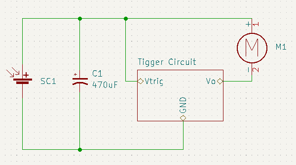
Original SymFlower circuit (pre-robotifcation).
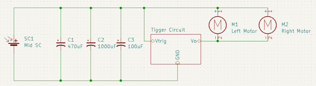
SymFlower V1 circuit with additional motor and capacitors.
SymFlower worked great until I dropped it; chipping the solar cell. After that traumatic event, the solar engine would only trigger in ideal lighting conditions (just sitting in the sun during the day was no longer enough). So I recently bought three new solarcells and wired them up to replace the original.
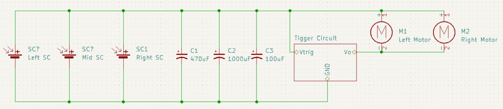
SymFlower V2 circuit with all three solar cells.
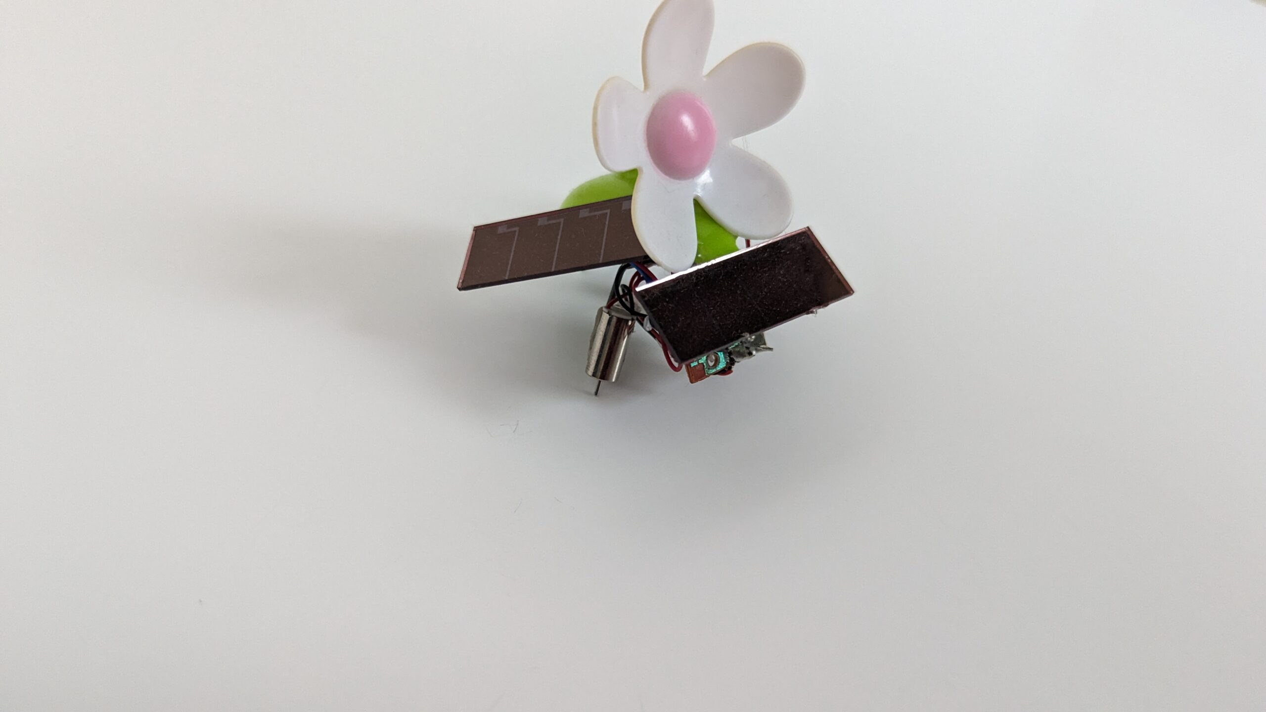
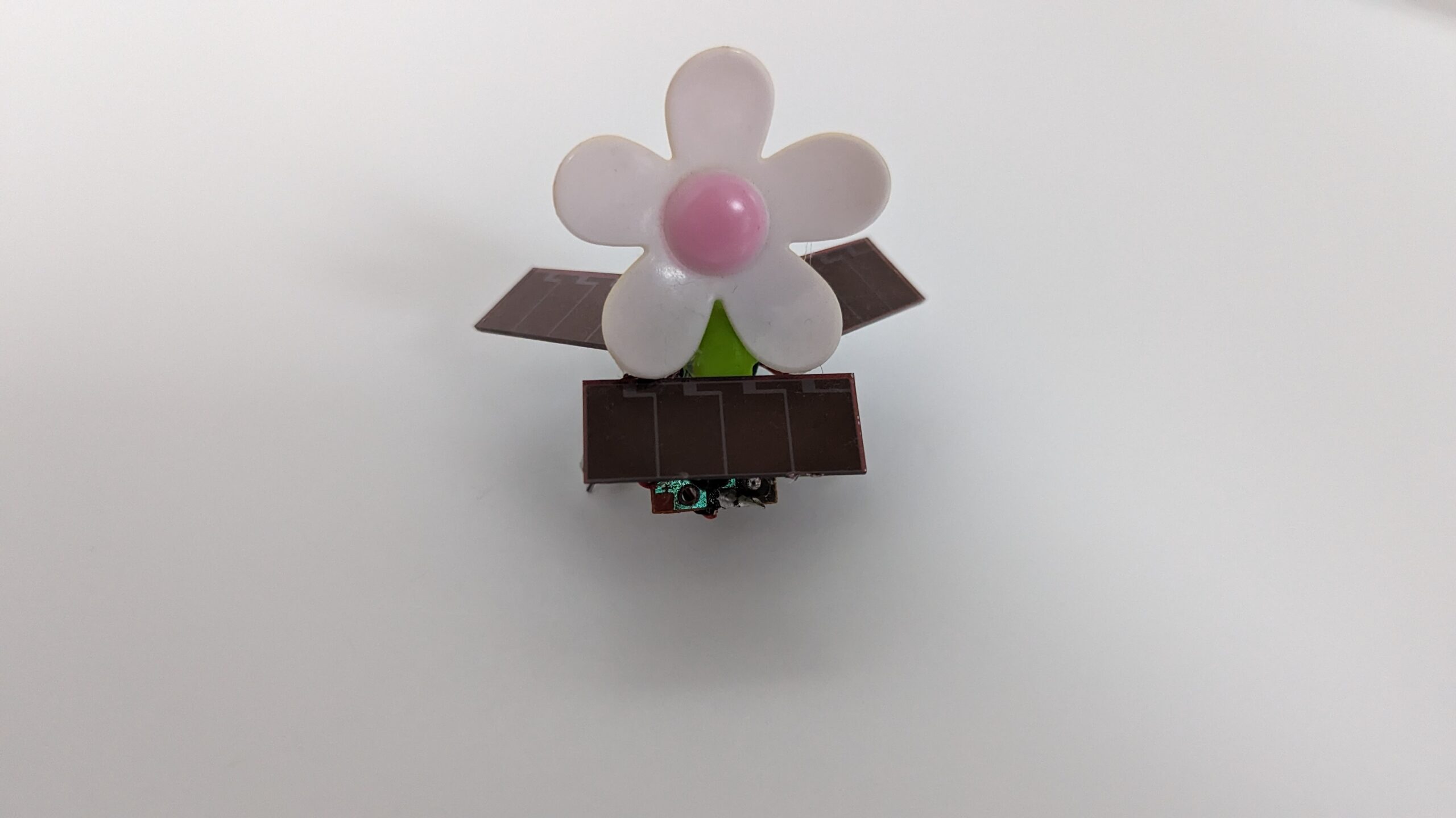
I think the final result looks great. I really like how the two wings allow it to collect some light even if the robot isn’t directly facing the sun.
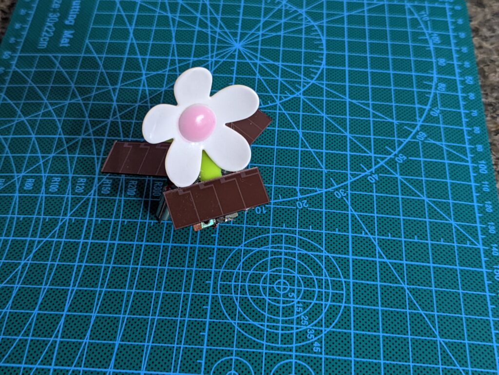
SymFlower V2 ~ Not sure if its actually a Symet but but it behaves like one.
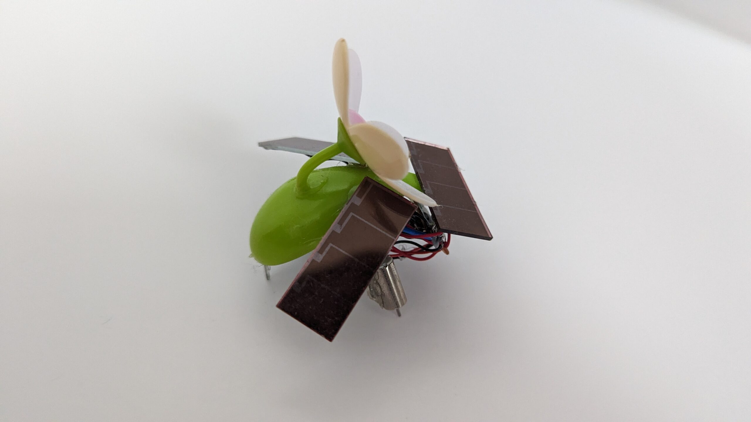
Some additional photographs of SymFlower:
Op-Amp Based Robots
Herbie the Photovore
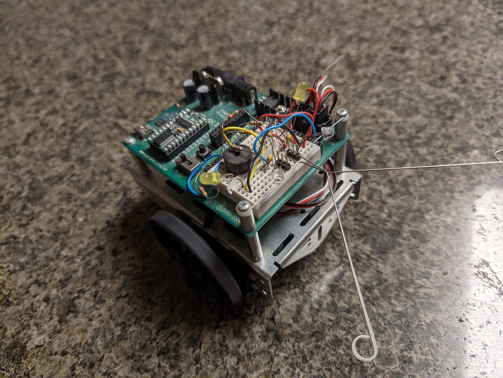
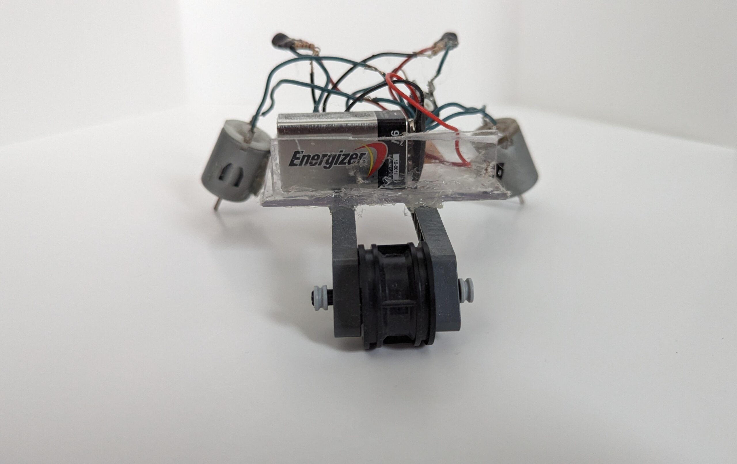
The next robot I built from the book, Junkbots, Bugbots, and Bots on Wheels, was Herbie. This robot is a photovore – meaning it seeks light.
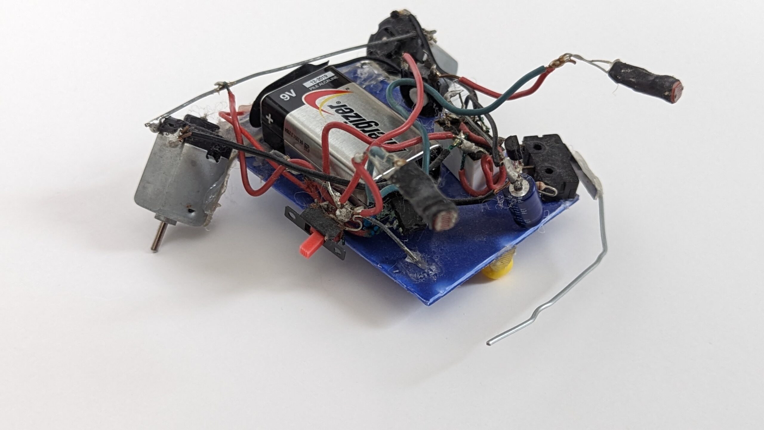
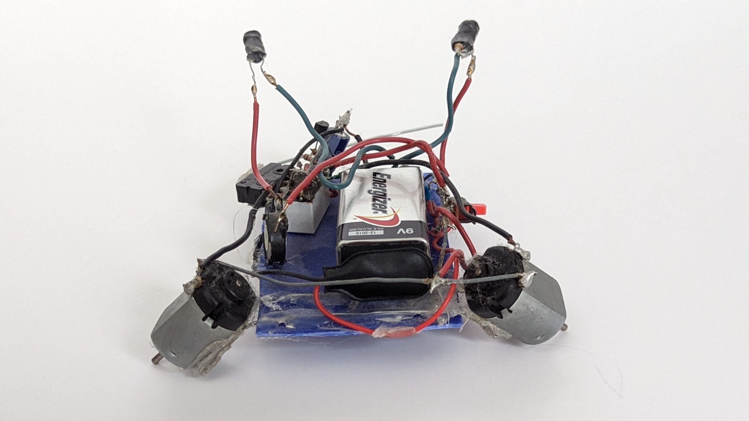
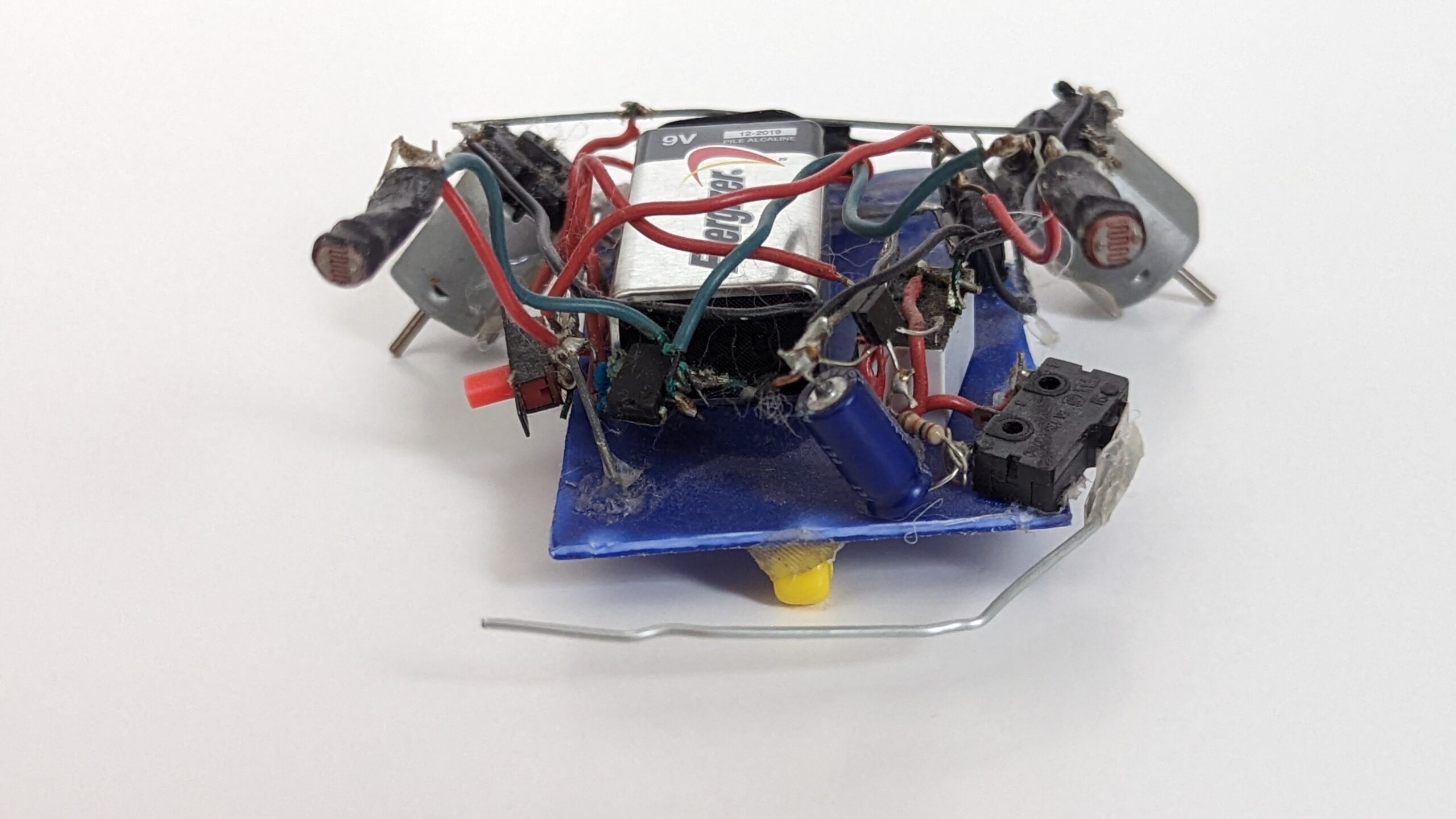
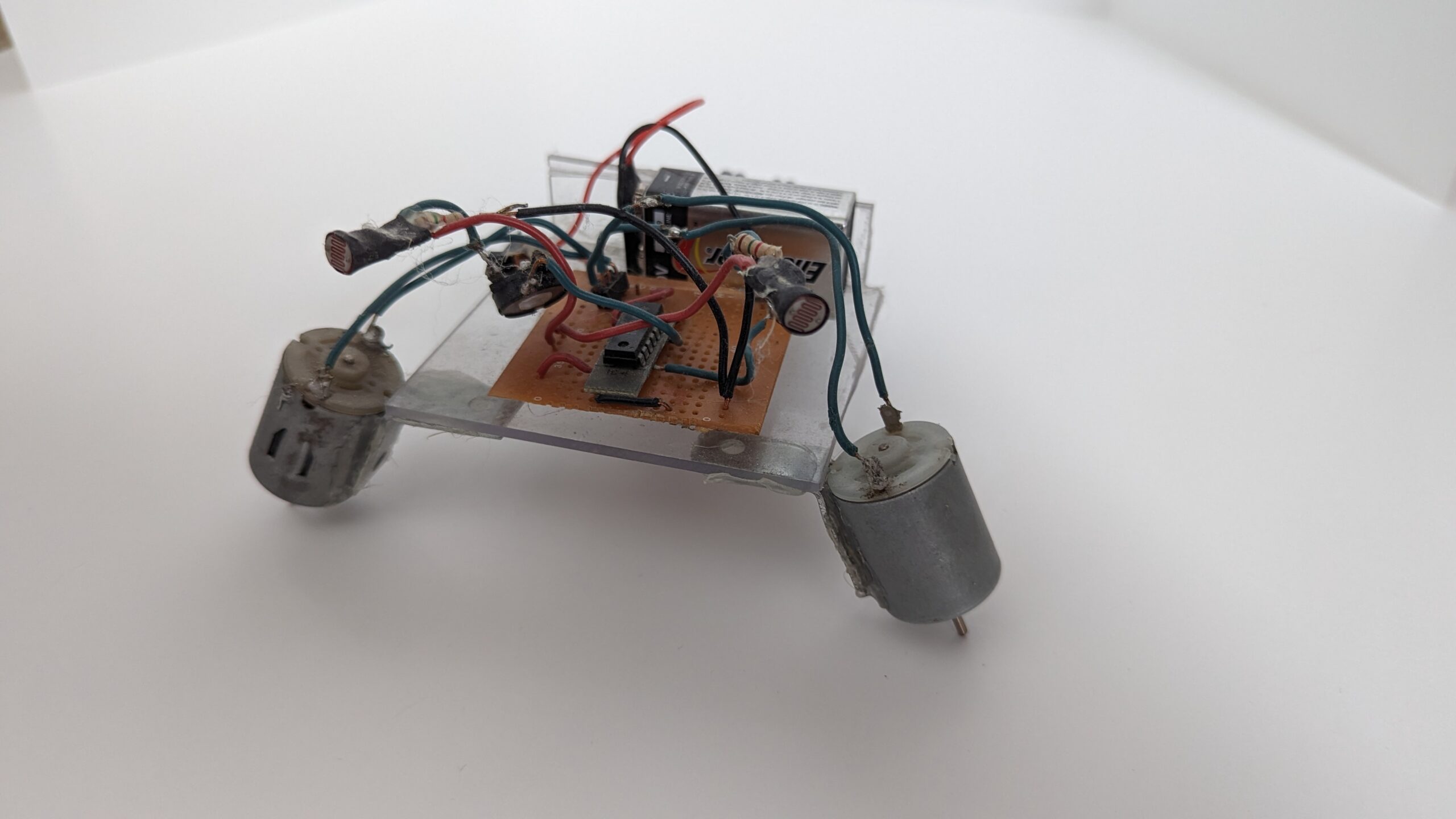
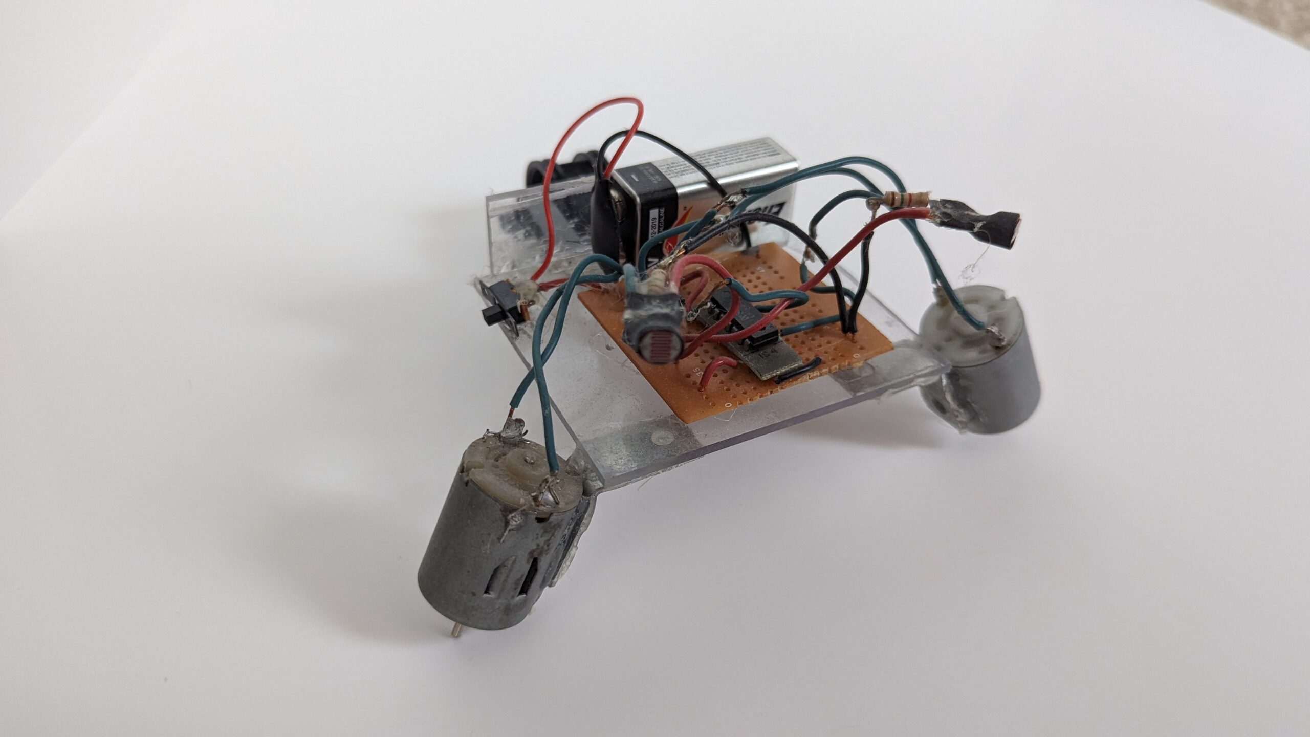
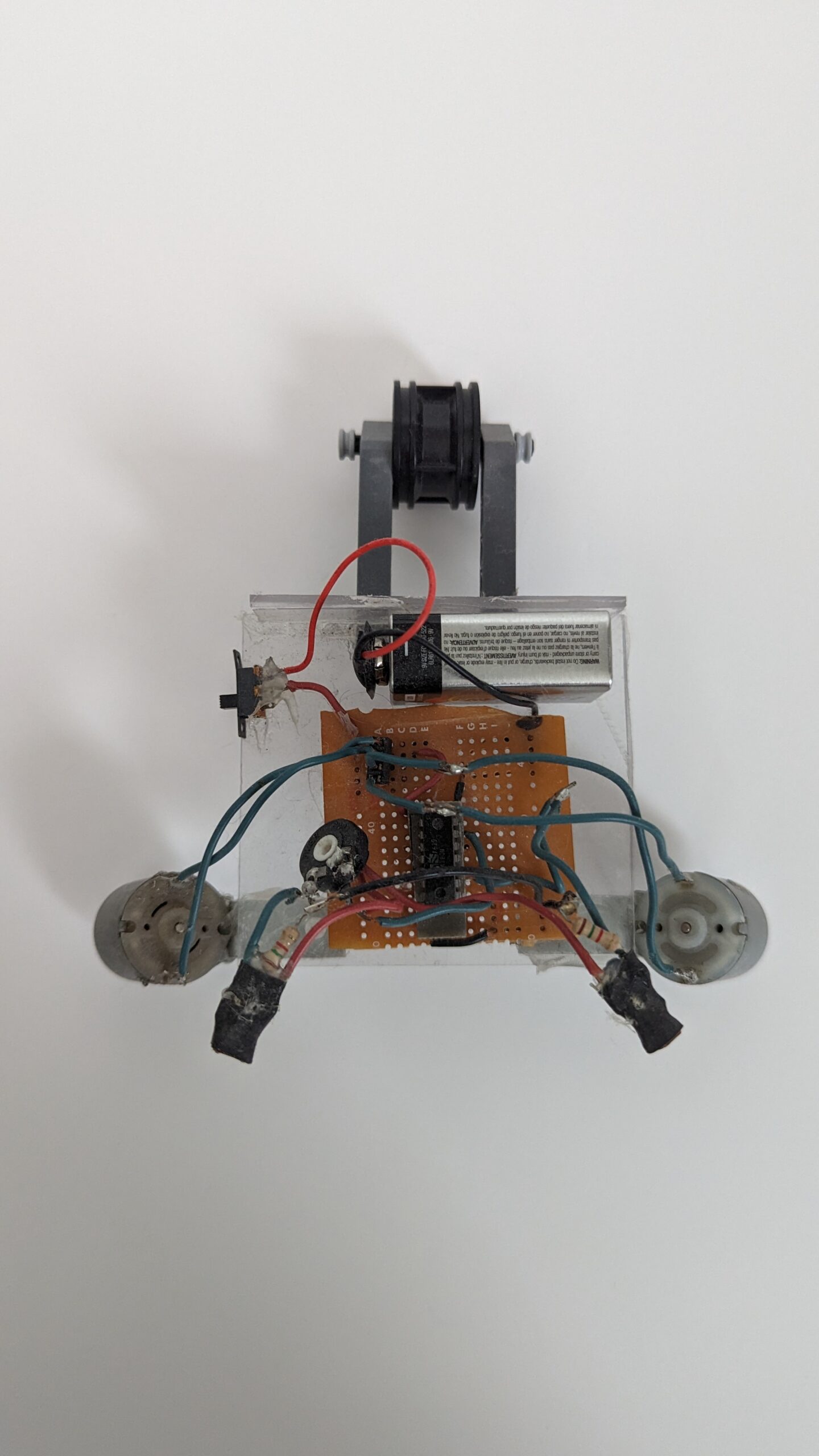
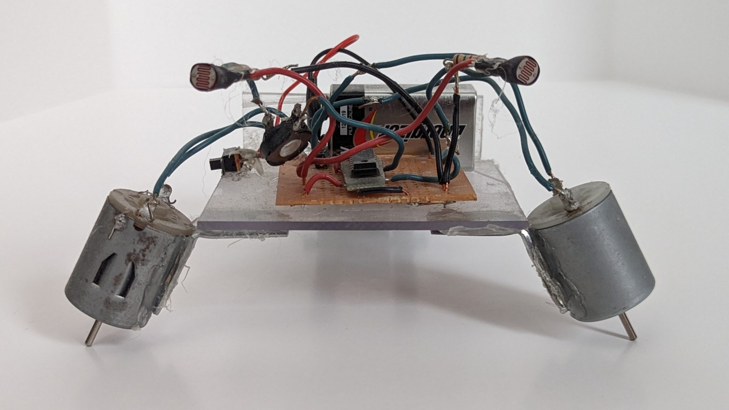
Herbie ~ A photovore bot built around a LM386 Op-Amp. Design from Junkbots, Bugbots, and Bots on Wheels.
Herbie’s circuit is based off the design proposed in Junkbots, Bugbots, and Bots on Wheels. The circuit works by using a LM386 op-amp to detect the difference between two light sensors. The op-amp will produce an intermediate voltage based on the difference between the inputs. By then connecting one motor from positive voltage to intermediate and the other from intermediate to ground level the op-amp can control two motors. Each motor experiences a voltage drop (resulting in motion) relative to this variable intermediate level.
There is also a reverse circuit consisting of a resistor and capacitor network that triggers a switching transistor for a short period of time. By adjusting the resistor and capacitor one can effectively change the on-time of the transistor after the detection switch opens back up.
This transistor then sinks the switching current for a relay that flips the directionality of the motors (much like what happens on the switches in the Beetle bots).
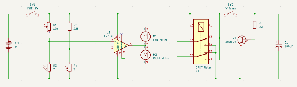
Schematic for an LM386 Herbie robot. Photoresistor values are unknown but probably in the low kilo-ohms.
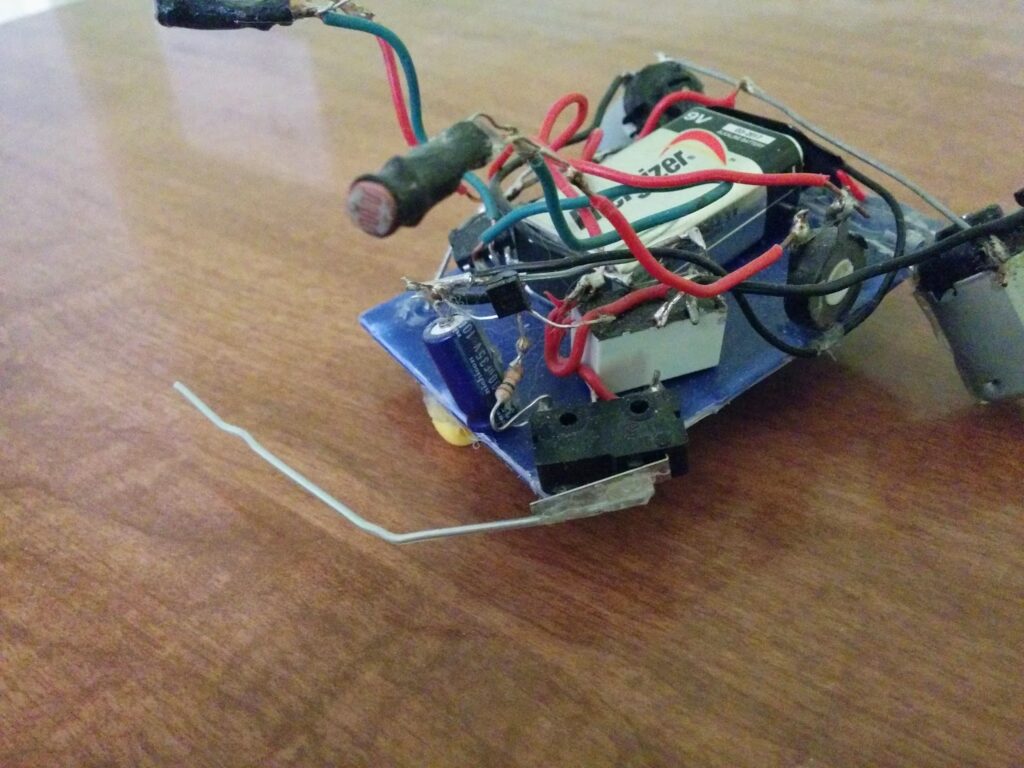
While writing up this post on Herbie, the most glaring problem was the rats-nest of wiring. It wasn’t well thought-out when originally constructed. For instance, the power switch is only attached with a solid core wire that bends a bit each time the switch is flipped. If I were to make another (or if you wanted to), I would suggest in putting more thought into how this should be wired up first. Also, the design could be condensed. The way I built Herbie has the components spread out, but it would be more interesting if the design was made as compact as possible. This rats nest does solve the problem of keeping the 9V battery secured though; so that’s a point in favor.
There is also an issue with the RC circuit I used for reverse timing. The circuit seems to oscillate between forward and reverse states after the button was pressed even if it successfully removed itself from the obstacle (which is a whole separate issue).
Lastly, the reverse functionality flips both motors. This results in a sub-optimal backwards reverse behavior followed by it switching back to moving forward again (and most likely re-ramming into the object). I am proposing for the next version to have two whisker collision switches (like the Beetles).
Even with all the negatives, this was a great robot to build while learning about basic BEAM robotics. The op-amp sub-circuit is very useful for creating photovore behavior. The reverse sub-circuit is also a good tool to keep in the toolbox. Additionally, there is a bit of subsumption architecture being demonstrated in this design. Specifically, the relay switching from default photovore to higher order reverse behavior.
Solarbotic sells a freeform kit here and a PCB kit here.
Some additional photographs of Herbie:
NoBB (November Basement Build)
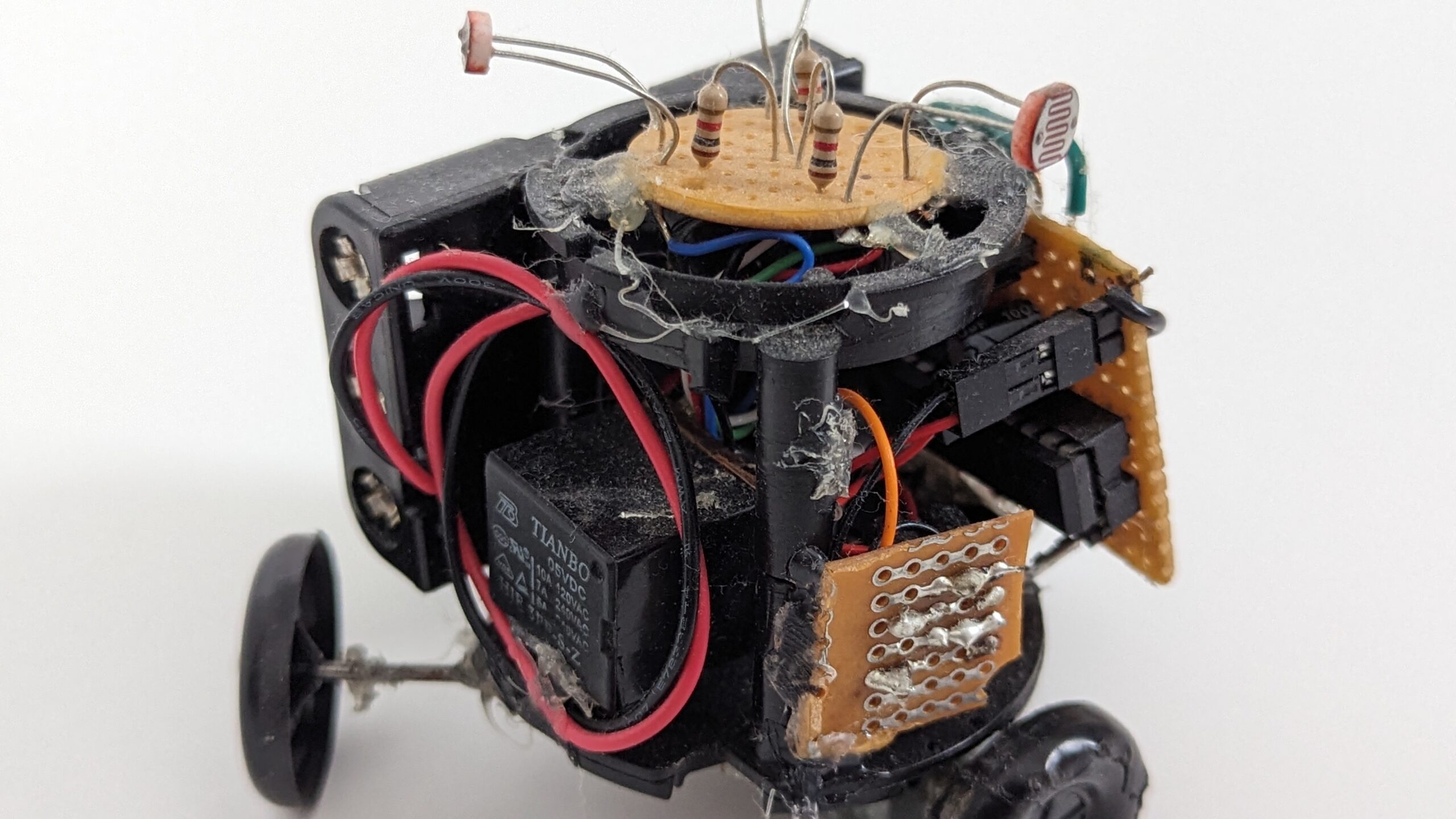
One weekend in November I had a bit of free time and decided to build a simple BEAM robot out of parts lying around the shop. I ended up building NoBB (a.k.a. November Basement Build). Its a simple photovore designed like the LM386 Herbie robot. I used an op-amp salvaged from an old school intercom. The motors were taken from a motorized Hot Wheels toy (my siblings and I had a lot of motorized toys it seems). The two CdS photo-resistors were spares from the Herbie project.
NoBB ~ A photovore built around an Op-Amp salvaged from a school intercom.
The schematic for NoBB is simpler than Herbie as I didn’t build in the backup behavior. This was to be a quick and dirty build that lasted me a few hours during the weekend. There are a few janky thinks happening. The eye “stalks” aren’t the cleanest and the LM380 is still attached to the PCB that was cut out from the intercom. However, the design is much cleaner than the rats-nest that was Herbie. Also it is nice that the power switch was properly secured with some hot glue this time. Lastly, using some bent right angle brackets make a nice motor mount.
Schematic for NoBB; a simplified Herbie circuit without the backup subsystem. Photoresistor values are unknown though probably in the low kilo-ohms?
Reflecting back, there are a few things that could be improved. First, the trim-pot used was too large and should not be in series with another constant resistor. The op-amp, LM380, was also not as sensitive as the LM386. These two issues made the photovore behavior very weak. Only in a dark room with a singular point light source does this robot demonstrate any change in behavior. The second main problem was using two salvaged motors from different toys. While they externally look similar, they do not spin at close to the same rate. This causes the robot to heavily drift when it should be going straight. I used a wide, stiff rear caster to mitigate some of this drifting with minimal success.
Some additional photographs of NoBB:
Closing Thoughts
My early journey through robotics was informed by BEAM. Through these simple robots I got to learn basic electronics skills (e.g., reading schematics, wiring circuits, soldering) and some core robot maker principles (touch sensor whiskers, photovore behavior, subsumption architecture).
I recommend everyone to try constructing some BEAM robots. I found Dave and Mark’s book, Junkbots, Bugbots, and Bots on Wheels, to be an invaluable resource. Some of the salvaging techniques work less now that we are past the age of VCRs and through-hole components but none-the-less the circuits and concepts within are timeless.
Feel free to comment and give feedback. Until next time, keep building.