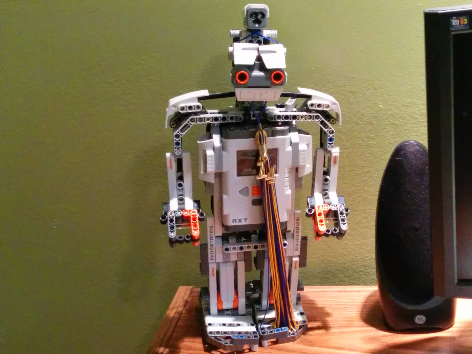
RoverBot is an RC car hack gone wrong (but with plenty of lessons learned along the way).
To set the scene, I was in early high school having built a few BEAM robots and finished up the LEGO Mindstorms and BOE-Bot kits. It was time to start my own microcontroller robot project with the new fangled Arduino that I was hearing about. Years later (in undergrad) I came back to tinker for round two. Then by the time I moved to California, RoverBot needed a tune-up.
The code can be found on Github.
Attempt #1
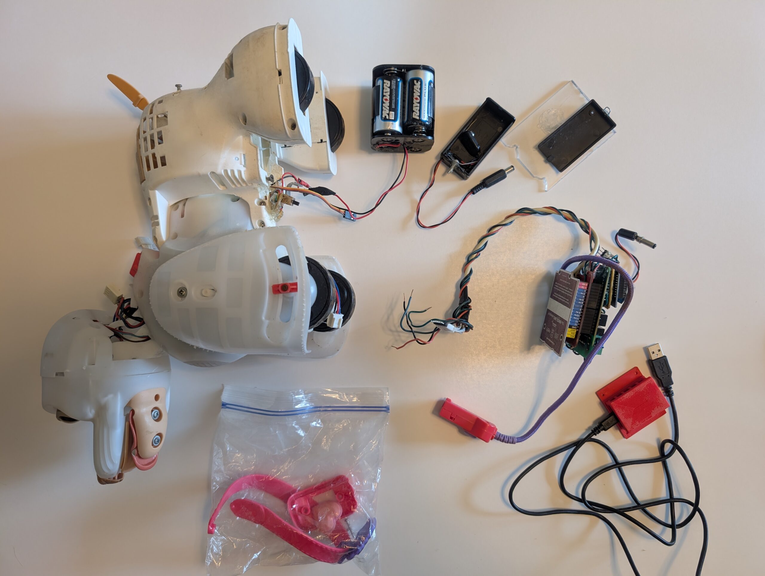
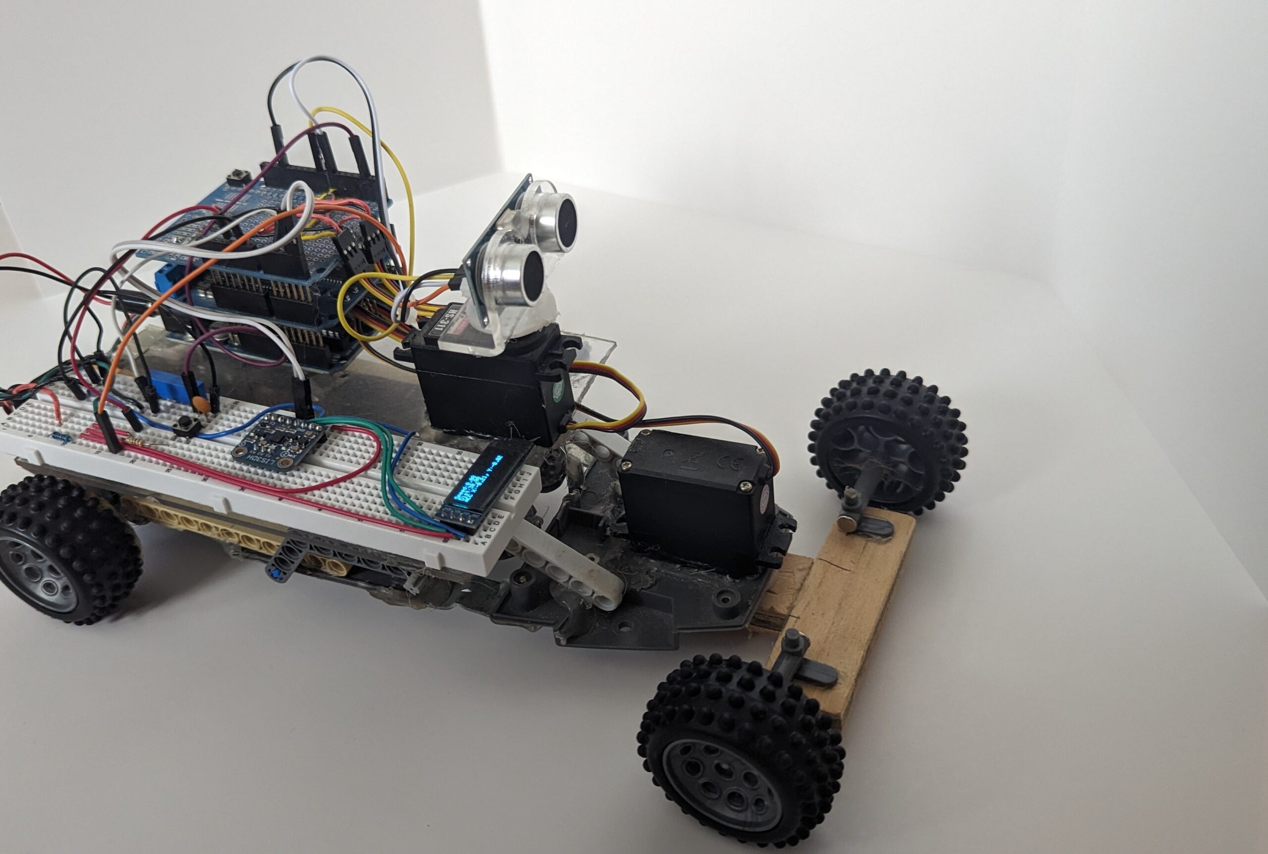
I had an RC car toy lying around and set out to remake it as an autonomous robot. First I took the enclosure off the robot and gutted the electronics. Then I removed the front motor and turning assembly; replacing it with a servo motor I bought from the local hobby store. I built a little shelf out of polycarbonate and some spare LEGO Technic pieces to hold an Arduino Uno stack-up. Lastly, I mounted a servo with a Parallax Ping ultrasonic sensor as its head for collision detection.
The Arduino Uno stack-up consists of (from bottom to top):
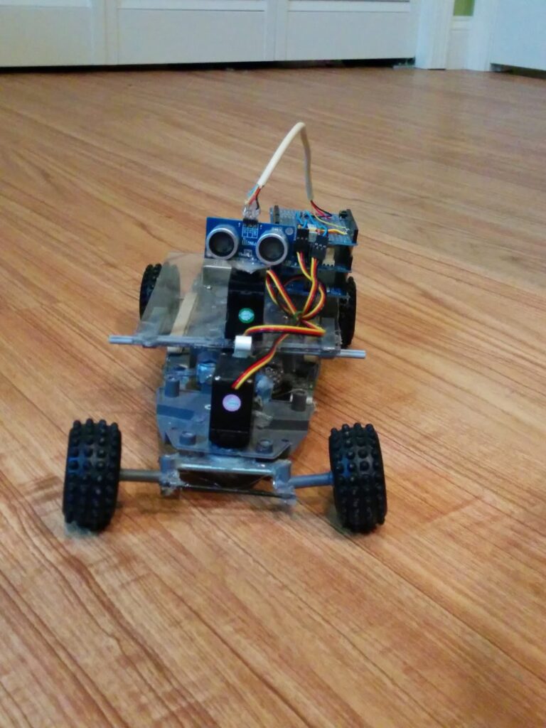
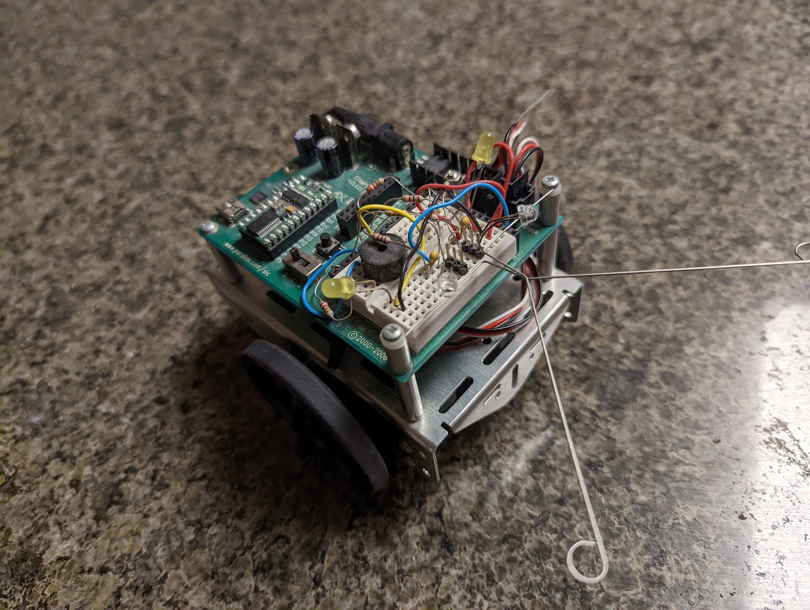
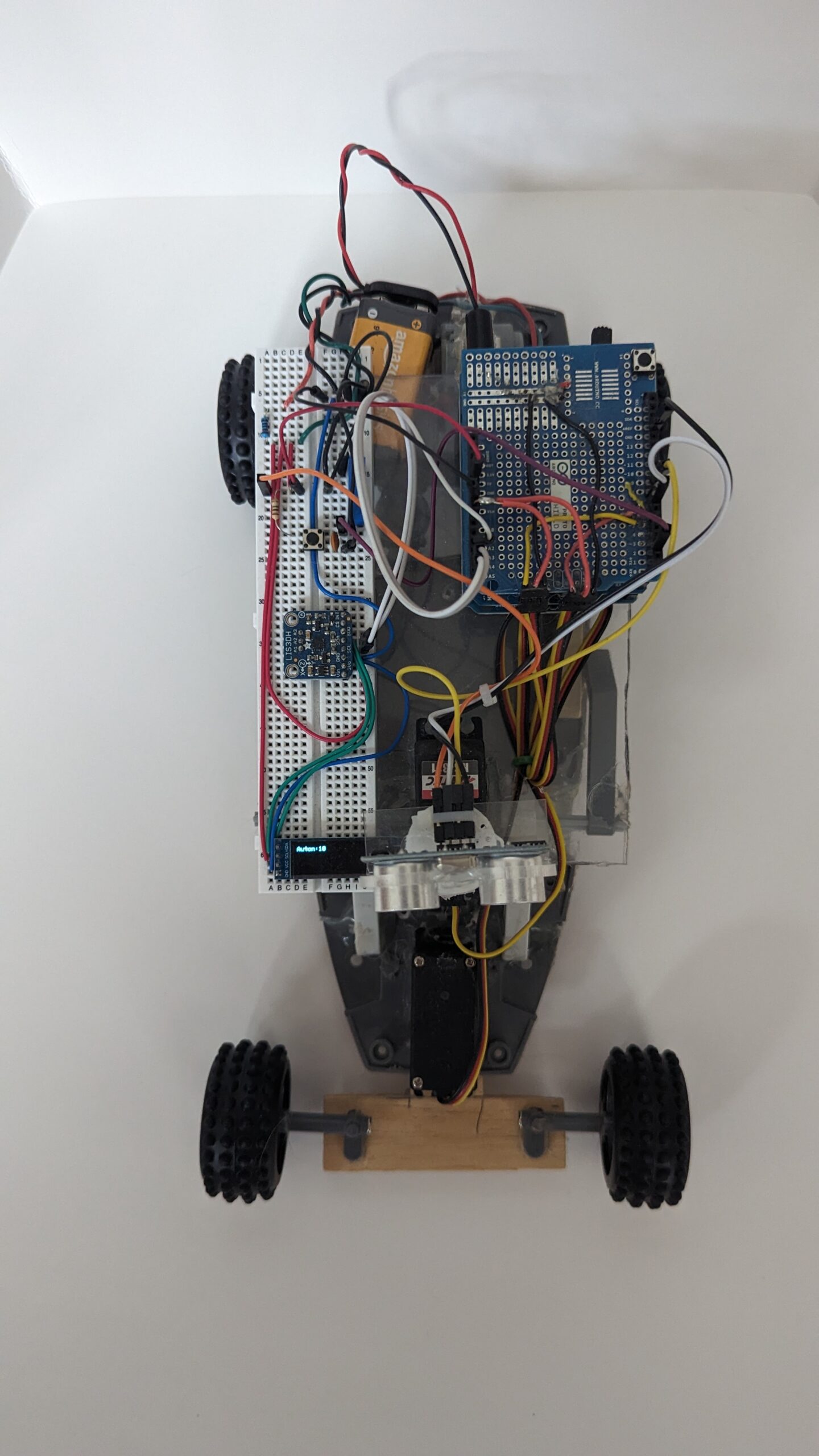
Chassis stripped down to its bare bones. I built a platform using plexiglass and some spare LEGOs. The front wheels sagging pretty much captures the jankiness of the project.
The code was written such that it would drive forward till it came within the distance threshold was reached. at which point it determined if it braked in time for it to turn or if it needed to back up first. Then it would determine which way it should turn to get the larger distance (by turning the head servo left and right). After committing to a turn direction for a short period of time, it would straighten out (or potentially stop and reassess if the distance threshold was reached during turn).
One of the main challenges was not the evasive action algorithm but the forward and backward driving. Depending on the surface (hardwood, short carpet, or medium carpet) RoverBot’s speed would vary greatly. For example, when driving on carpet it goes slower and thus needs a lower distance threshold, but on hard surfaces the robot would collide with the wall. I spent way too much time tuning the open loop parameters and never got a satisfactory implementation.
I will discuss the firmware in greater detail for attempt two since that is the final state of the project.
When backing up, the motor would shift just enough to lose connection between the motor shaft drive gear and the gearbox. I “solved” this with “careful” application of hot glue and bits of plastic.
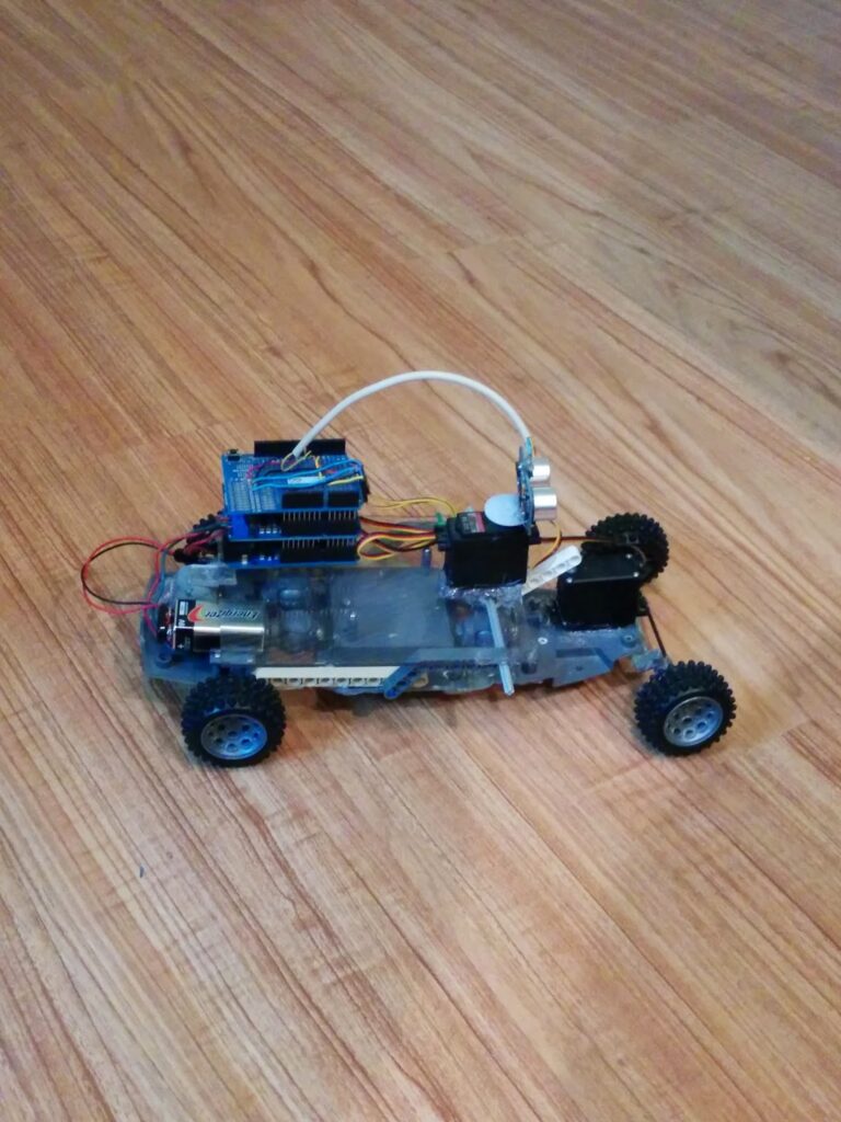
Regarding power, I used a 9V battery to power the electronics and servos and 4x AA batteries (6V) for the drive motor. Mechanically, I reused the battery box embedded within the RC car chassis, which was a good choice. But I didn’t make as good of a choice with the 9V battery wedged between the chassis and the polycarbonate shelf.
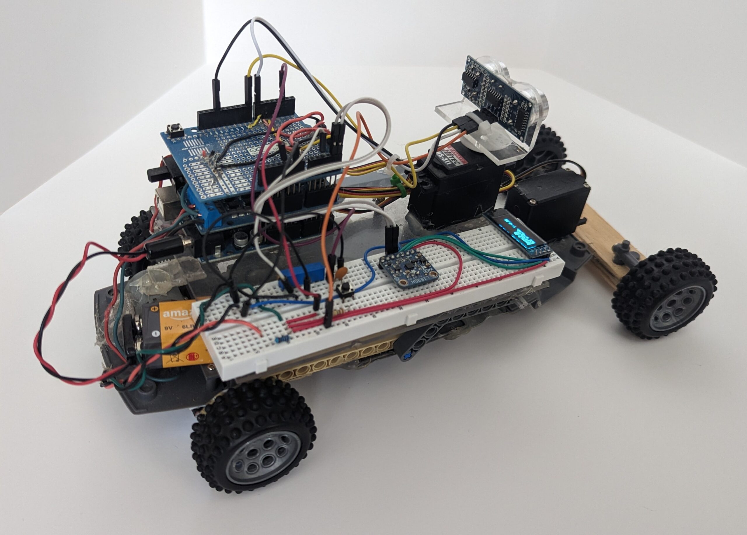
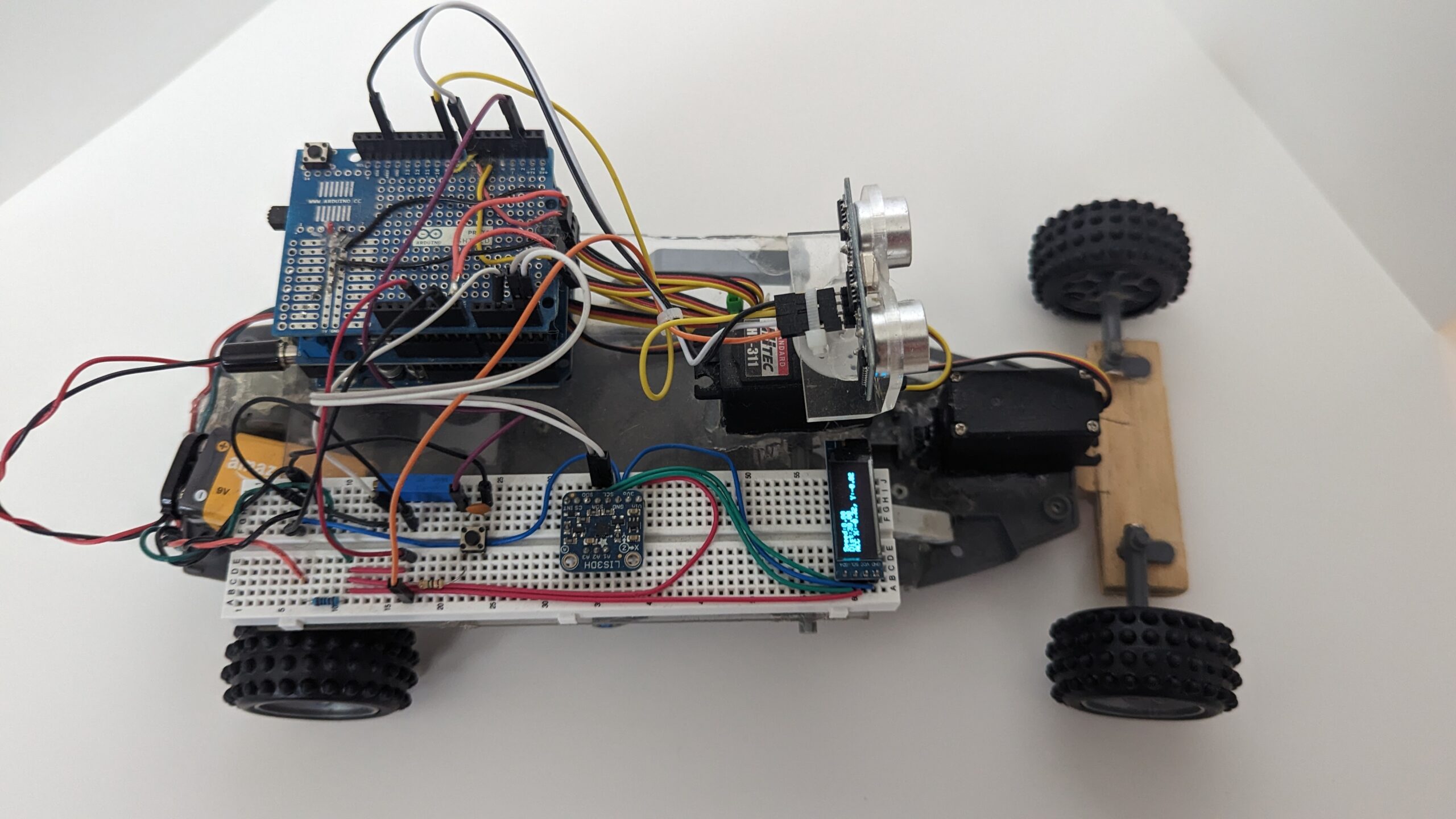
Side profile of RoverBot. Wiring was pretty clean but chassis was definitely not mechanically sound.
The following is what I outlined I wanted to do in the future
With the open space on the side of the Arduino, I would like to add either a display to read variables off, battery level, and allow for me to change to different presets for different floor types. I would like to use a voltage sensor in order to actively control the speed better, and to stop signaling servos (somehow, maybe relays) so that we can get a solid ping when the 9V battery gets low.
Some of these things would be addressed in attempt two.
Attempt #2
After taking a break on RoverBot in high school / undergrad for other projects, I finally came back. Most of my work was addressing some of the shortcomings of my original system. Unfortunately, I did not take good notes of my work at the time so the following is documentation of the current state. I will try to make note of things I tweaked again when I repaired it after my move to California.
Hardware
The base hardware platform was inherited from attempt one. I needed to address a couple of things. First I replaced the original front wheel assembly with a bit of a sturdier wood unit. I spent some time shoring up the polycarbonate shelf with more LEGO pieces. RoverBot was finally looking a bit more rigid.
Electronics were also improved. I kept the basic stack-up and battery system but augmented them with a homebrew encoder on the drive wheels, and accelerometer, and an OLED display. Plus these new electronics were placed into a solderless breadboard for easier prototyping.
California refresh notes:
- I had to replace the Ping ultrasonic sensor when I moved to California. The old one was completely non-functional. I went with a no-name, cheap HC-SR04 unit from Amazon. Same math, slightly different pinout.
- I also swapped out the accelerometer. The old one was analog and drifted horribly. I replaced it with an I2C LIS3DH from Adafruit.
The following schematic captures the current state of RoverBot.
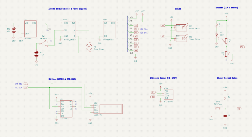
Schematic for RoverBot with stack-up top-left, I2C bus bottom left, and various sensors and servos right.
There are a couple of things going on that are worth noting.
First, shown in the top-left is a simplified view of the Arduino stack-up with power supplies. Each Arduino shield is shown connected by a BUS which is just a simplified representation of the pins interconnecting between boards. Note, I removed the VIN connection between Arduino at +9V and the motor controller shield with VIN at +6V.
Second, I don’t have notes on the resistors / capacitor values used. These specific values don’t matter that much. One just needs to pick values that make sense together for your system.
Homebrew Encoder
I needed some way of measuring motor stall in order to close-the-loop and thus solve the carpet versus hardwood driving conditions parameter search I found myself in during attempt one.
My solution involved printing the following pattern onto some paper, cutting out the circle and gluing it to the drive wheel.

Encoder printout to be cutout and attached to the wheel. Pair with an LED and light sensor to track the light-dark pattern when wheel rotates.
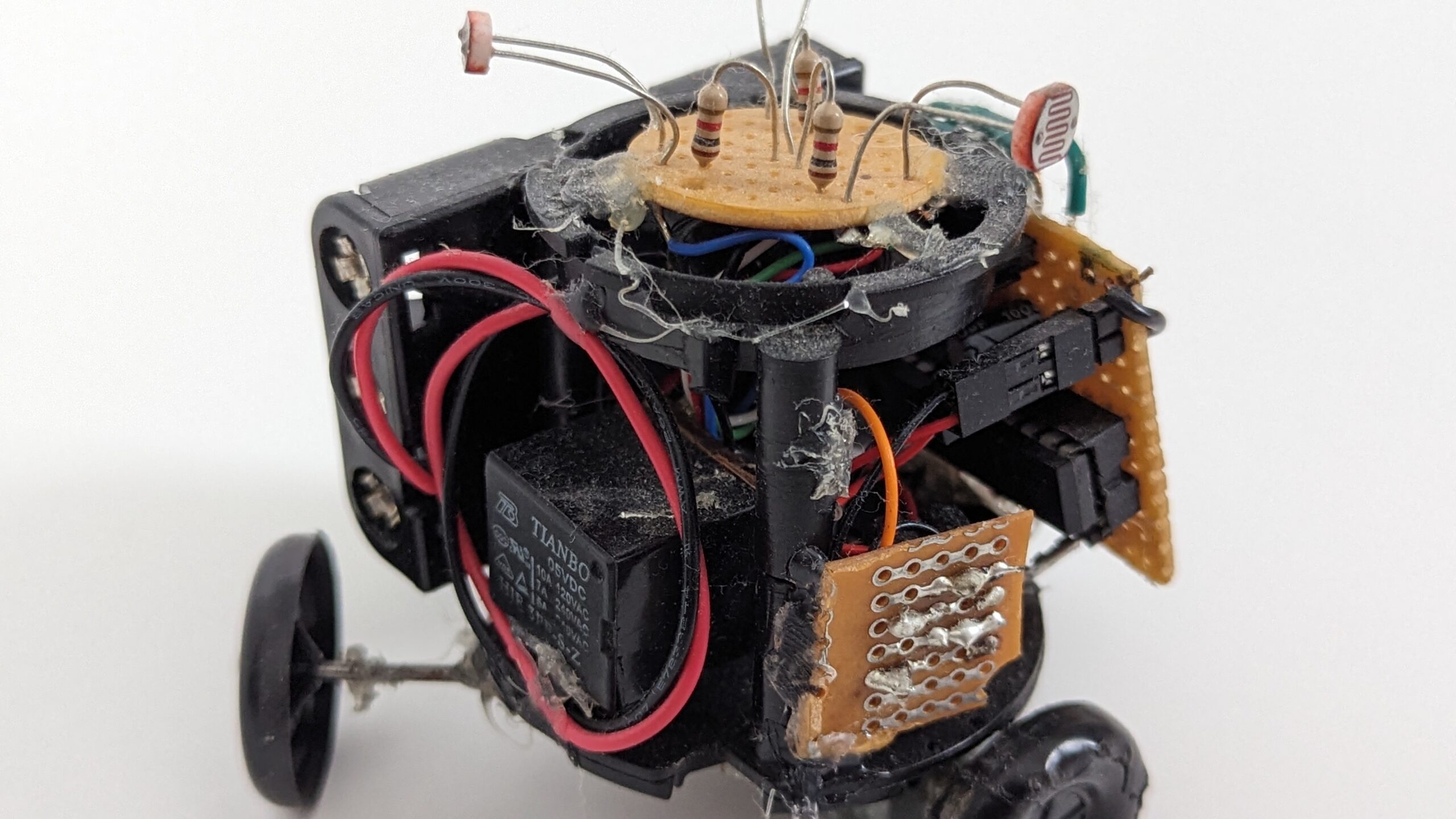
With the light-dark pattern in place, I wired up a LED and CdS photoresistor pointed at the wheel (but tried to keep them isolated from each other the best I could with electrical tape). Then by detecting changes in voltage as the wheel turned in front of the sensor I could get a pulse count, which could be converted into revolutions per second.
Software
The greatest time investment was in software. I had to write the drivers for the new hardware and revamped the original spaghetti code into a state-machine.
I will walk through some of the important snippets but won’t cover everything. Please checkout my Github for the full source code.
Main
The main file should be kept as simple as possible. Below is the full thing, excluding imports.
Nomenclature: KISS (keep it simple stupid) is an important engineering mantra to remind ourselves not to overengineer or complicate things.
static Hardware _roverHardware;

void setup(void) {
  Serial.begin(9600);

  _roverHardware.begin();
  auto_reset();
}

void loop(void) {
  _roverHardware.update();
    auto_update(_roverHardware);
  delay(1);
}
Perhaps its a bit too simple. If I were to do it again, I would bring some kind of test harness setup here as well.
Low-Level hardware configuration is defined below. It usually makes sense at the scale of an Arduino project to have a manifest of all the pins used; all relevant serial communication; and anything else that’s general purpose HAL like setting up a debug pin.
Nomenclature: HAL (Hardware Abstraction Layer) is an embedded engineering term to describe the hardware interface we define for our application. It is often a layered implementation starting with a wrapper of your hardware registers all the way up to abstract system functions that an application may request. One uses a HAL to decouple the application from the low-level details of operating on real hardware.
//==============================================================================
//                              Device Pinout
//==============================================================================

#define HW_SERIAL_RX_PIN                    0
#define HW_SERIAL_TX_PIN                    1
#define DISPLAY_BUTTON_PIN                  2
#define MOTOR_CONTROLLER_PWM_PIN            3
#define STEER_SERVO_PIN                     5
#define HEAD_SERVO_PIN                      6
#define ULTRASONIC_TRIGGER_PIN              7
#define ULTRASONIC_ECHO_PIN                 8
#define MOTOR_CONTROLLER_BRAKE_PIN          9
#define MOTOR_CONTROLLER_DIRECTION_PIN      12

#define DONT_USE_A0_PIN                     A0
#define DONT_USE_A1_PIN                     A1
#define ENCODER_PIN                         A3
#define I2C_SDA_PIN                         A4
#define I2C_SCL_PIN                         A5

//==============================================================================
//                              Debug Serial
//==============================================================================

#define DEBUG_SERIAL                        Serial
#define DEBUG_SERIAL_BAUD                   9600

//==============================================================================
//                            I2C Address Space
//==============================================================================

#define I2C_DISPLAY_ADDRESS                 0x3C
#define I2C_ACCEROMETER_ADDRESS             0x18
Drivers
I won’t go into too much detail for standard drivers as there is plenty of example code online.
I wrapped the following into a HAL:
- Accelerometer : Using Adafruit LIS3DH library
- Display : Using Adafruit GFX and Adafruit SSD1306 libraries
- Ultrasonic : Borrows from example code for sending and receiving a pulse
- Motor Controller : Borrows from example code for controlling Arduino motor shield
- Servo : Using Arduino Servo Library
- Encoder : Uses Arduino AnalogRead
Encoder Implementation
The encoder was the only real custom device. Its pretty simple:
#define UPDATE_TIME               150 //! Calculate new speed interval
#define ANALOG_ENCODER_THRESHOLD  350 //! Light value mapping (from experiment)
#define TICKS_PER_REV             4.0 //! Encoder conversion

/**
 * Samples ticks of the encoder and determines speed on event. Call every
 * main event loop.
 */
void Encoder::update(void) {

  bool nextState = analogRead(analogPin) > ANALOG_ENCODER_THRESHOLD;
  if (nextState != encoderState) {
    encoderState = nextState;
    count++; //tick
  }

  if (updateTimer >= UPDATE_TIME) {
    updateTimer -= UPDATE_TIME;
    speed = (count / (UPDATE_TIME /  1000.0)) / TICKS_PER_REV;
    count = 0;
  }
}

/**
 * @return gets the current speed in rev / sec
 */
float Encoder::getSpeed(void) {
  return speed;
}
In abstract:
- Read analog voltage and compare to pre-calibrated threshold for light / dark.
- If different from current state then increment tick.
- (Note this could actually be oscillating and it would look like a normal revolution).
- Recalculate the speed periodically and store into cached variable.
The key constraint is we need to sample the encoder update loop fast enough to measure the brightness transition. Nyquist says at least two times the frequency (of the motor time ticks) in order to capture the signal. Arduino should be plenty fast if we write our code correctly.
I never spent time attempting to address issues due to non-ideal environments such as the sun hitting the sensor at just the right angle. In a real encoder there would be a shroud to shield the sensor from environmental factors.
Display Implementation
This is a driver that I wish I had written differently. It makes a couple assumptions about dataflow that “work” but are not well engineered. I should have structured the driver as a layered GUI stack semi-independent of RoverBot’s internals.
The display serves as the frontend for RoverBot. It has the I2C OLED itself and an associated press button (though we handle the button in the hardware abstraction layer).
Display has a set of pages that it cycles through on a timer. Each page contains relevant, grouped state variables. The button when pressed stops scrolling until pressed again, giving users more time to read or monitor particular variables. Scrolling is not handled here but in the hardware layer. Only the page render functions are defined.
Page List:
- Autonomous
- State Code
- Sensors
- Encoder Speed
- Ultrasonic Distance
- Accelerometer X
- Accelerometer Y
- Motors
- Head Servo Angle
- Steer Servo Angle
- Drive Motor +/- PWM
- + is forward
- – is backward
Robot Hardware
I wrote a generalized HAL for the robot platform using the various drivers written (and somewhat tested). The main goal is to provide a robot-level interface with action primitives. For instance, if you tell the robot to go forward it should. If it needs to speed up (as an example) this layer should handle it not some higher-level system.
Hardware provides the following hooks to lower-level in-case these are needed:
- getHeadServo
- getSteerServo
- getUltrasonic
- getMotorController
- getDisplay
- getAccelerometer
Along with some robot-level primitive actions:
- forward
- backward
- forwardLeft
- forwardRight
- backwardLeft
- backwardRight
- turnHeadRight
- turnHeadLeft
- centerHead
- stopMoving
- isStuck
And some life-cycle hooks needed for module operation:
- begin
- update (to be called periodically in main loop)
Lastly, we break the clean coupling by providing a hook for higher-level to inform low-level state (but for display purposes only):
- setAutonStateCode
- A better way to do this would be for hardware to own a list of callbacks that would report relevant variables to display. But this would go against the KISS principle.
There are a few implementation details to consider. First, let’s define some motor control constants. These are predefined variables that I spent way to much time tuning in high school.
//Steering Servo constants
#define STEER_SERVO_CENTER                 85  //degrees
#define STEER_SERVO_LEFT                   110 //degrees
#define STEER_SERV0_RIGHT                  60  //degrees

//Head Servo constants
#define HEAD_SERVO_CENTER                  85  //degrees
#define HEAD_SERVO_LEFT                    50  //degrees
#define HEAD_SERVO_RIGHT                   120 //degrees

//Default motor speeds
#define MOTOR_REVERSE_SPEED                 190 //pwm
#define MOTOR_FORWARD_SPEED                 160 //pwm
#define MOTOR_FORWARD_TURN_SPEED            200 //pwm
Implementation of the motion primitives is pretty straightforward (we will come back to the speed controller within these primitives).
/**
 * Commands Roverbot's to move forward
 */
void Hardware::forward(void){
  speedController.isCommandedToMove = true;
  steering.write(STEER_SERVO_CENTER);
  motorController.forward(MOTOR_FORWARD_SPEED + speedController.speedOffset);
}

/**
 * Commands Roverbot's to move backward
 */
void Hardware::backward(void){
  speedController.isCommandedToMove = true;
  steering.write(STEER_SERVO_CENTER);
  motorController.reverse(MOTOR_REVERSE_SPEED + speedController.speedOffset);
}

/**
 * Commands Roverbot's to turn left and move forward
 */
void Hardware::forwardLeft(void){
  speedController.isCommandedToMove = true;
  steering.write(STEER_SERVO_LEFT);
  motorController.forward(MOTOR_FORWARD_TURN_SPEED + speedController.speedOffset);
}

/**
 * Commands Roverbot's to turn right and move forward
 */
void Hardware::forwardRight(void){
  speedController.isCommandedToMove = true;
  steering.write(STEER_SERV0_RIGHT);
  motorController.forward(MOTOR_FORWARD_TURN_SPEED + speedController.speedOffset);
}

/**
 * Commands Roverbot's to turn right and move backward
 */
void Hardware::backwardRight(void){
  speedController.isCommandedToMove = true;
  steering.write(STEER_SERVO_LEFT);
  motorController.reverse(MOTOR_REVERSE_SPEED + speedController.speedOffset);
}

/**
 * Commands Roverbot's to turn left and move backward
 */
void Hardware::backwardLeft(void){
  speedController.isCommandedToMove = true;
  steering.write(STEER_SERV0_RIGHT);
  motorController.reverse(MOTOR_REVERSE_SPEED + speedController.speedOffset);
}

/**
 * Commands Roverbot's to turn right but not move
 */
void Hardware::turnHeadRight(void){
  head.write(HEAD_SERVO_RIGHT);
}

/**
 * Commands Roverbot's to turn left but not move
 */
void Hardware::turnHeadLeft(void){
  head.write(HEAD_SERVO_LEFT);
}

/**
 * Commands Roverbot's to center head for forward movement but not move
 */
void Hardware::centerHead(void){
  head.write(HEAD_SERVO_CENTER);
}

/**
 * Commands Roverbot's to stop moving.
 */
void Hardware::stopMoving(void){
  speedController.isCommandedToMove = false;
  motorController.stop();
}
Next let’s define the speed controller structure that will help figure out if RoverBot is stuck and adjust PWM offset for speed control.
// Different categories of speed used to classiy encoder output
typedef enum SpeedBins {
  SPEED_STUCK,      //! Speed is approximatly zero and should not be
  SPEED_SLOW,       //! Speed could be higher
  SPEED_NORMAL,     //! Speed is just right :}
  SPEED_HIGH,       //! Speed could be lower
  SPEED_INVALID     //! Speed is not zero and should be
} SpeedBins_t;

// Speed controller update constants
#define STUCK_COUNT_THRESHOLD               5
#define UPDATE_SPEED_CONTROLLER_TIME        200 //ms

/**
 * Bang-bang closed loop speed controller which tries to stay within a speed
 * bin.
 */
typedef struct SpeedController {
  bool isCommandedToMove;       //! Robot should be moving
  int appearsStuckCount;        //! Number of times speed was classified as stuck
  elapsedMillis updateTimer;    //! Time event to update controller state
  int speedOffset;              //! Offset on the drive motor PWM
} SpeedController_t;
Given the tracking in primitives, we can update the speed controller:
/**
 * Computes new state of the speed controller on timing event
 */
void Hardware::_updateSpeedController(void) {
  if (speedController.updateTimer >= UPDATE_SPEED_CONTROLLER_TIME) {
    speedController.updateTimer -= UPDATE_SPEED_CONTROLLER_TIME;

    // classify
    float speed = encoder.getSpeed();
    SpeedBins_t bin;
    if (speedController.isCommandedToMove) {
      if (speed <= 0.5) {
        bin = SPEED_STUCK;
      } else if (speed <= 5) {
        bin = SPEED_SLOW;
      } else if (speed <= 8) {
        bin = SPEED_NORMAL;
      } else {
        bin = SPEED_HIGH;
      }
    } else {
      if (speed > 0.5) {
        bin = SPEED_INVALID;
      } else {
        bin = SPEED_NORMAL;
      }
    }

    // compute stuck
    if (bin == SPEED_STUCK) {
      speedController.appearsStuckCount += 1;
      if (speedController.appearsStuckCount > STUCK_COUNT_THRESHOLD) {
        speedController.appearsStuckCount = STUCK_COUNT_THRESHOLD;
      }
    } else {
      speedController.appearsStuckCount -= 1;
      if (speedController.appearsStuckCount < 0) {
        speedController.appearsStuckCount = 0;
      }
    }

    // compute speed offset
    if (bin == SPEED_SLOW || bin == SPEED_STUCK) {
      speedController.speedOffset += 10;
      if (speedController.speedOffset >= 50) {
        speedController.speedOffset = 50;
      }
    } else if (bin == SPEED_HIGH) {
      speedController.speedOffset -= 10;
      if (speedController.speedOffset <= -10) {
        speedController.speedOffset = -10;
      }
    } else if (bin == SPEED_INVALID) {
      speedController.speedOffset = 0;
    }
  }
}
This function does a few things we should discuss:
- Periodically updates the controller based on a software timer
- This is good to prevent updating too quickly, before hardware has a chance to react
- Non-blocking, allowing other routines to run in the update loop
- Classify encoder signals into discrete speed levels (bins)
- Given the speed control is just a discrete adjustment on an open loop system it doesn’t make sense to have too much granularity in our signal
- Being stuck is simply the encoder speed bin of not moving (or moving way too slow) when you expected to be driving around.
- But we don’t want to oscillate between being stuck and not stuck each cycle. So we have a saturating counter that determines robot is stuck only when a number of cycles indicate the robot is likely stuck.
- This counter also decays back down to zero when not stuck.
- Instead of hard resetting back to zero, it limits the chance of a single erroneous not stuck reading from costing more time before stuck behavior is triggered.
- Computing speed offset is a simple way of somewhat closing the motor control loop without implementing a full closed-loop controller like PID.
- These offsets are used in the primitive actions.
Again, being stuck is simply when the speed controller stuck counter as incremented by the encoder state passes a threshold.
/**
 * @return true if the robot thinks it is stuck else false
 */
bool Hardware::isStuck(void) {
  return speedController.appearsStuckCount >= STUCK_COUNT_THRESHOLD;
}
Display is also handled in the robot hardware (though admittedly this was a poor choice). The following code snippet demonstrates the display update, freeze button logic, and the higher level state hook.
/**
 * @param state sets the internal state code cache (used for display)
 */
void Hardware::setAutonStateCode(byte state) {
  _autonStateCode = state;
}

/**
 * Checks current display frozen button toggle
 */
void Hardware::_updateButton(void) {
  byte pressed = !digitalRead(DISPLAY_BUTTON_PIN);
  if (pressed && !_previouslyNotPressed) {
    _displayFrozen = !_displayFrozen;
    _previouslyNotPressed = true;
  } else if (!pressed && _previouslyNotPressed) {
    _previouslyNotPressed = false;
  }
}

/**
 * Updates display page contents and rolls page if not frozen
 */
void Hardware::_updateDisplay(void) {

  if (_lastRefreshTime >= DISPLAY_REFRESH_TIME) {
    _lastRefreshTime = 0;

    switch (_displayPageIndex) {
      case 0:
        display.pageRender_auton(
          _autonStateCode
        );
        break;
      case 1:
        display.pageRender_sensors(
          encoder.getSpeed(),
          ultrasonic.getCachedDistance(),
          accelerometer.getX(),
          accelerometer.getY()
        );
        break;
      case 2:
        display.pageRender_motors(
          head.read(),
          steering.read(),
          motorController.getSpeed() * motorController.getDirection()
        );
        break;
    }
  }

  if (!_displayFrozen && _lastRolloverTime >= DISPLAY_ROLLOVER_TIME) {
    _lastRolloverTime = 0;

    _displayPageIndex++;
    if (_displayPageIndex >= 2) {
      _displayPageIndex = 0;
    }
  }
}
On first pass, it makes sense to have the display in the hardware layer. It mostly displays robot state information. But in retrospect, I would have liked to see a parallel module for display that is has render data request callbacks that can be configured independently / generally.
Autonomy State-Machine
A robot wouldn’t be interesting if it just sat there doing nothing.
For RoverBot I implemented the autonomy loop as a main loop state machine (as you may recall from the main setup() and loop() functions). The algorithm is pretty much the same wall-banging routine as attempt one. Refer to the state machine diagram for details:
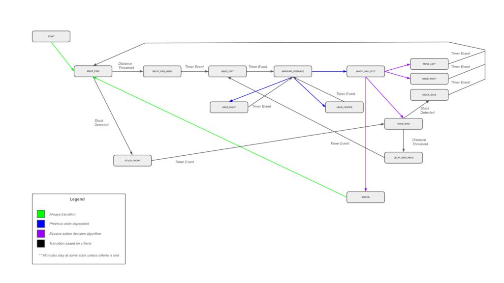
Autonomy State-Machine for RoverBot.
The state-machine is implemented as a switch-case that dispatches a function call that generates the next state. The following table describes the state functions and their operations.
| State Code | Algorithm | Next State |
| START | NA | MOVE_FWD |
| MOVE_FWD | If timer event Measure distance If distance < threshold Stop moving Else If stuck Stop moving Else Drive forward | DELAY_FWD_HEAD if distance threshold met STUCK_FRONT if stuck MOVE_FWD otherwise |
| MOVE_BWD | If timer event Stop Moving Else If stuck Stop moving Else Drive backward | DELAY_BWD_HEAD if distance threshold met STUCK_BACK if stuck MOVE_BWD otherwise |
| MOVE_LEFT | If not timer event Drive forward left | MOVE_FWD if timer event MOVE_LEFT otherwise |
| MOVE_RIGHT | If not timer event Drive forward right | MOVE_FWD if timer event MOVE_RIGHT otherwise |
| HEAD_LEFT | If timer event Stop moving Set variable before measure Else Turn head left | MEASURE_DISTANCE if timer event HEAD_LEFT otherwise |
| HEAD_CENTER | If timer event Stop moving Set variable before measure Else Center head | MEASURE_DISTANCE if timer event HEAD_CENTER otherwise |
| HEAD_RIGHT | If timer event Stop moving Set variable before measure Else Turn head right | MEASURE_DISTANCE if timer event HEAD_RIGHT otherwise |
| MEASURE_DISTANCE | Read distance from ultrasonic Decide next state | HEAD_RIGHT if variable was left distance HEAD_CENTER if variable was right distance WHICH_WAY_SLCT if variable was center distance ERROR otherwise |
| WHICH_WAY_SLCT | Decide next state | MOVE_BWD if corner detection threshold reached MOVE_BWD if center distance less than threshold MOVE_LEFT if left distance greater or equal to right distance MOVE_RIGHT otherwise |
| STUCK_FRONT | If not timer event Drive backward (or attempt to) | MOVE_BWD if timer event STUCK_FRONT otherwise |
| STUCK_BACK | If not timer event Drive forward (or attempt to) | MOVE_FWD if timer event STUCK_BACK otherwise |
| DELAY_FWD_HEAD | Wait for timer event (Robot is drifting to a stop) | HEAD_LEFT if timer event DELAY_FWD_HEAD otherwise |
| DELAY_BWD_HEAD | Wait for timer event (Robot is drifting to a stop) | HEAD_LEFT if timer event DELAY_BWD_HEAD otherwise |
| ERROR (or default) | Stop moving Reset state machine | START |
One thing added to this attempt was the corner detection system developed for BOE-Bot. Recall, the detector checks for oscillations with turning left and right indicating the robot is stuck in a corner and needs to back up first.
I paired this corner algorithm with the stuck delay increase algorithm. When stuck it takes progressively longer durations of attempting to force in the opposite direction before continuing on with the state-machine.
Future Work
I never did get the accelerometer integrated into the control loop. The data is being polled and displayed on the OLED for diagnostics. There could be some future work to improve the stuck detector and speed controller logic with the accelerometer.
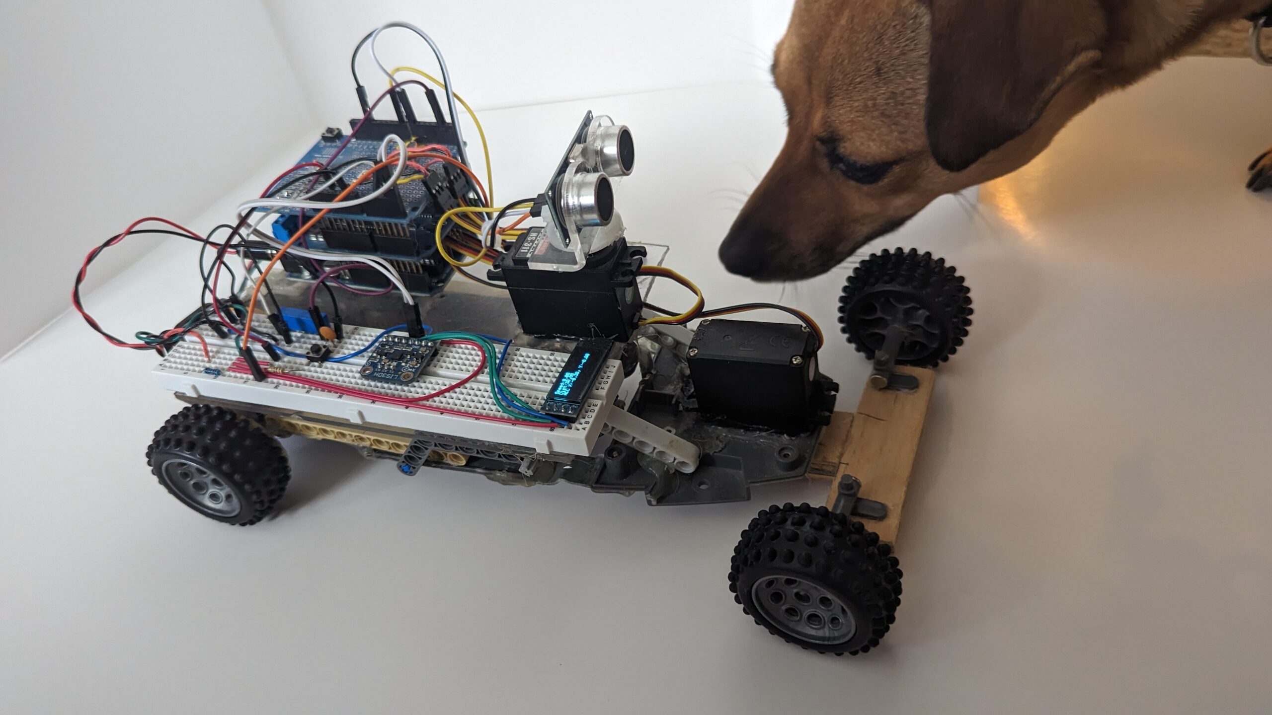
Photoshoot
The following is a photo gallery from RoverBot from a mini-photoshoot I did.
Closing Thoughts
I want to close this post by discussing two relevant thoughts. First considering the high-level architecture that emerged from RoverBot development over the years. Second, considering the HAL in abstract from an embedded system perspective.
Thought One: RoverBot autonomy is a state-machine implementation but it is also the top levels of a subsumption architecture.
Nomenclature: Subsumption Architecture is a behavior-based approach that organizes a robot’s behavior into layers, with each layer responsible for a specific task. Higher layers can subsume (or suppress) the output of lower layers to control the overall behavior of a robot.
Below is the subsumption architecture diagram start on the left-bottom with sensors, moving through the subsumable control layers, and on the right low-level motor control primitives.
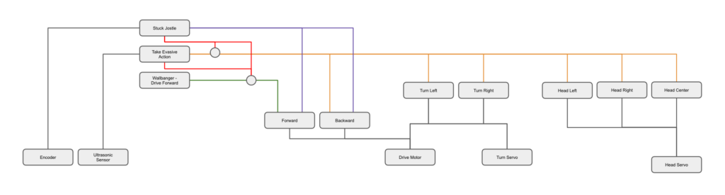
Subsumption Architecture for RoverBot.
Low-level primitives map to our drivers (HAL) whereas the autonomy is a state-machine stacked on top of driver forward with take evasive action (stopping, turning and corner detection) and on top of that stuck detection with forward / backward jostling.
Thought Two: HAL is a layered collection of utilities and control algorithms to decouple low-level details from the high-level application. For RoverBot, the goal was to partially decouple the autonomy algorithm from the robot hardware. As discussed, the Hardware class mirrored the electrical implementation owning a MotorController, UltrasonicSensor, Accelerometer, Encoder, Servo, and Display classes. These each wrapped functionality of their specific subsystem.
I think generally it is a good idea to start with the fundamental building blocks. These are often libraries provided by your board vendor (Arduino, ESP, STM32, etc.). Once you have decent control over the hardware at this level, wrap the logic semantically. The next layer above shouldn’t need to know how to jog a couple pins for Arduino, it just needs to know that the dashboard LEDs are illuminating a status code. Repeat for each layer, sprinkling in the control loops as needed, preferably in a non-blocking manner.
For robotics, we can think of writing the HAL as the representation of the subsumption architecture in code. Only provide the details that the specific level needs nothing more. Let the lower levels define their world interaction.
Writing a good HAL also helps with properly testing the various bits of your robot before you start running the full autonomy loop as you can test out the functionality independently.